Aimsun Next: Yunex UTC Interface
Architecture
The communication between Aimsun Next and a Yunex UTC with SCOOT uses CORBA. The exchange of information is: from Aimsun Next to Yunex UTC, the detector information; from Yunex UTC to AIMSUN, the stage information.
Relationship between Aimsun objects and SCOOT objects
To guarantee a correct connection between Aimsun Next and Yunex UTC, it is necessary to make sure that SCOOT objects have a one-to-one correspondence with Aimsun objects. Therefore the following rules must be adhered to:
-
SCOOT controller: Each SCOOT controller has to be represented in Aimsun Next as one SCOOT-type controller (ASCOOTCont).
-
SCOOT Intersections: One SCOOT intersection must be represented by one Aimsun junction. The ASCOOTCont must be connected to the Aimsun junction that corresponds to the SCOOT intersection.
-
SCOOT Connection: SCOOT controllers can connect to different IP Addresses.
-
SCOOT Stages: The Aimsun model must contain the same phases defined in the control plan as the Stages defined in the SCOOT model. In the control plan definition in Aimsun Next the requirements are:
- The control type of all intersections controlled by SCOOT must be defined as External.
- The control plan definition in an intersection with Pedestrians needs to include the pedestrian and the vehicle phases (with their interphases). Each phase of this type of intersections requires the Minimum Duration definition because when SCOOT changes from a pedestrian stage to a vehicle stage (or vice versa), Aimsun Next changes the phase when the minimum time defined by the user is reached.
-
SCOOT Detector: Each SCOOT detector should be modeled with a corresponding Aimsun detector. If the detector corresponds to one physical detector (either stage detector or SCOOT detector) then the Aimsun detector must have, at least, Occupancy and Presence as measuring capabilities. If this detector represents a detector for Transit then the modeled detector must have Equipped Vehicle as a measuring capability. All transit lines associated with Transit detectors have to be modeled as Transit lines with 100% of Equipped vehicles in their Vehicle Types.
Aimsun Next - SCOOT interchange information
Aimsun Next and SCOOT interchange of information (synchronization tokens, detector measures, stages, etc.) takes place every second as one of SCOOT's requirements. The detection cycle should therefore be set to 1 second. If the simulation step is not 1 second, the data synchronization rules apply.
SCOOT objects definition in Aimsun Next
The definition of the SCOOT objects is done in Aimsun Next and it is based on first defining the SCOOT preferences, then defining one SCOOT type controller in the model corresponding to each real SCOOT controller.
A double-click will open the dialog window associated with the controller:
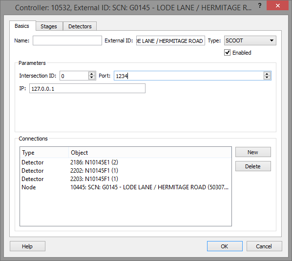
In the Basics tab the options are:
- Intersection ID: SCOOT Intersection Identifier
- Port: SCOOT connection port
- IP: SCOOT IP Address
- Connections: Defines the connections between the controller and those devices under its control. Links are made using the New button or the Connection tool. All nodes and detectors controlled by SCOOT must be connected.
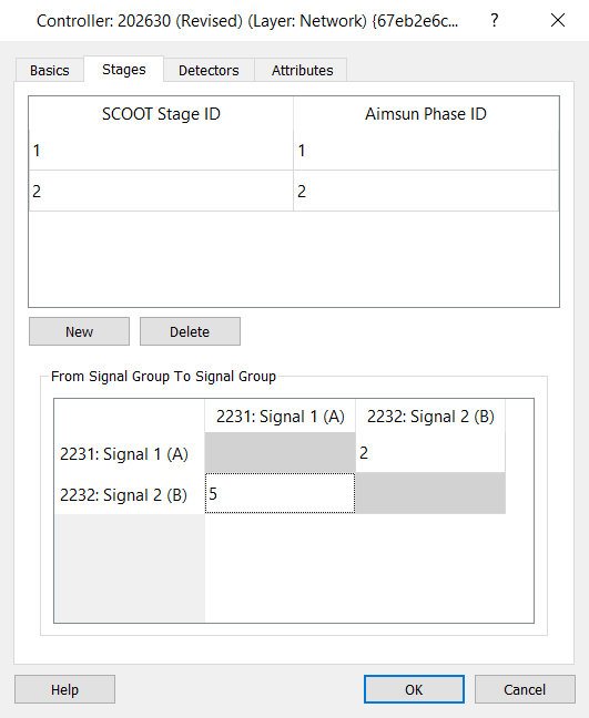
Stages Tab
The second step is to establish the controller's links to the signal stages. Each SCOOT stage has:
- Scoot Stage ID: this is the SCOOT identifier.
- Aimsun Phase ID: this is the phase in the Aimsun model that corresponds with the stage defined in SCOOT.
The From Signal Group to Signal Group table defines the intergreen delay time between the signal groups in the controlled junction as defined in the Node Editor.
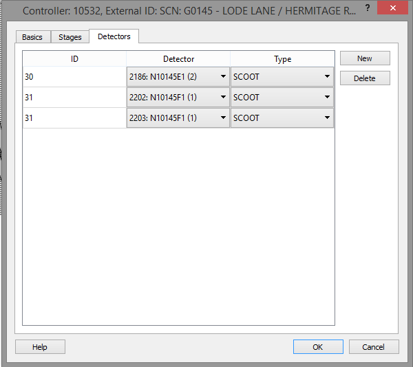
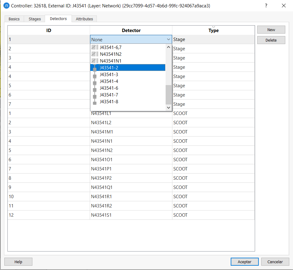
Detectors Tab
The third step is to establish the controller's links to the associated detectors. To add a new SCOOT detector:
- Click on the New button.
- Set the ID.
- Select a detector from the list of detectors connected to the controller.
Each SCOOT detector has as attributes:
-
ID: represents the SCOOT identifier.
-
Detector: is the Aimsun detector associated with this SCOOT detector.
-
Type: defines the SCOOT type detector. The type could be:
- SCOOT (generally the detectors located upstream)
- Stage (in order to send the stage demand)
- Push-Button (in order to represent the pedestrian demand)
- Transit (in order to represent the transit priority)
In particular, for detectors of Stage type, the controller connected to UTC (SCOOT) sends presence assuming that each demand detector corresponds to one and only one physical detector. In case the detector ID is repeated for two or more detectors in the network, it works as an OR only. In some cases (e.g. in USA to mimic ring/barriers with multiple alternative demand dependent stages) the output of a demand detector can be an AND or an AND NOT processing of the output of multiple physical detectors. To allow the functionality of sending presence for one or more detectors, the user should first define a trigger under Traffic Management folder with two or more detectors that send presence data to the UTC SCOOT.
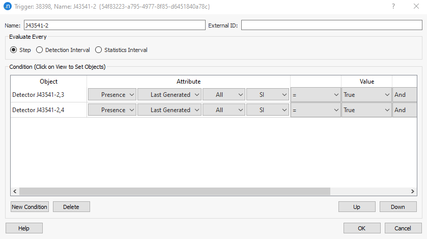
In the controller, detectors tab, a stage detector can be then configured to send presence depending on that trigger.
Debugging
The Yunex UTC interface can be configured to produce debugging information. This option is selected in the Scenario Editor.When this option is active, Aimsun Next will generate log files stored in the same folder as the Aimsun Next document.