Nodes
A node is a point or an area in the network where sections are linked and where vehicles move onto their next section. A node has one or more origin sections, one or more destination sections, and a set of turns linking the entrances and exits. Turns are the movements allowed in a node; a turn connects an origin section with a destination section.
Within each turn there are connections which specify, for the origin and destination lanes of the turn, which ones are the exact lane to lane connection options the vehicles will consider. Between turns there might be conflicts and the corresponding conflict zones specify the pairs of connections and the areas where vehicles potentially clash and hence a vehicle can not enter a conflict zone if another is already in it.
Connections and conflicts are only used in dynamic simulations, where individual vehicles make discrete lane choices and must keep safety distances; they are not applicable to static models which only model flows and average delays at links and junctions.
There are two node editors. The Properties Editor gives access to the basic properties of the node, its turns, signals, yield priorities, and also provides a detailed view of the movements in the node. The Advanced editor gives access to the more detailed properties of the node, adjusting its lane connections and conflict zones.
Signals at a junction can be allocated to turns to control priorities at the junction and connected to a controller that manages the phase changes according to a Pre-timed (fixed controlled), Actuated or Adaptive strategy. Signal controllers are documented in the Controllers Section. Signal groups, the set of turn movements given right of way when a given traffic light turns green, are defined in the node.
Creating Nodes and Turns
A node is defined by its turns, therefore when creating a new turn, it will either belong to an existing node or automatically generate a new node.
Aimsun Next has the ability to generate nodes with all their associated turns automatically. Once all the sections that will enter or leave the node have been created, select them and click on the node creation tool (left icon below). Roundabouts also have an automatic editing tool (left icon below).

The node tool will then create the node and all of its turns according to a set of turn generation rules, or it will indicate an error if only one section is selected, or if the selected lanes are only entry or only exit lanes.
New sections can be included in an existing node by selecting the section and some, or all of the sections of the existing node, then clicking on the node creation tool. Existing turns will remain the same, and new turns for the new sections will be included.
Nodes can also be created by selecting the node tool and clicking in the model view, without any previous selection of sections. In the node editor, turns are created by pressing the New button then clicking first the origin and second the destination section.
Another method to create turns is the Connection Tool. Using the connection tool, select the tool, then select the "from" section and drag the mouse to the "to" section. The turn will be generated in the existing node. If the node does not exist, the connection tool will create a new connecting section instead.
Roundabouts
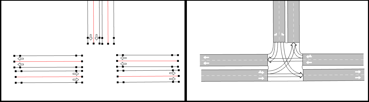
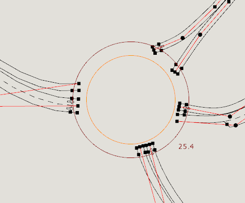
To create a roundabout, first create all the sections that will enter or leave the roundabout as shown on the next figure.
Select all the participating sections and click on the roundabout creation tool (right icon below).
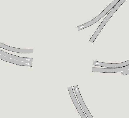
Then, in the center of the roundabout click left without releasing the mouse button, update the number of lanes, drag the mouse to the desired radius, and release. By default, the roundabout tool will create sections with the default number of lanes. To change this, press Ctrl + number of lanes before releasing the left mouse button. For example, Ctrl + 3 will create three lanes per section.
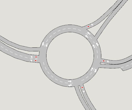
The roundabout tool might shorten the sections to maintain the chosen radius and will create the intermediate sections and nodes with the turns to build the final roundabout. These roundabout sections can subsequently be edited as normal sections to fine tune the shape of the roundabout.
Turn editing
Lane Use in Turns
Each turn has a set of entry and exit lanes. To see the lanes in use for a turn, open the node editor and select the turn either in the 2D view or in the turn table in the node editor. Lanes that use this turn will be colored in red.
The lanes used for the turn are selected by holding down the shift key and selecting multiple lanes for origin and destination section or, if the option Distinguish Destination Lanes in Turns is set (see Preferences Editor), then all lanes are selected by default.
In addition to specifying the lanes that are used for a turn in the origin and destination sections, the specific trajectories that vehicles will follow (from which lane to which lane within the turn) can be visualized hovering the mouse over the turn, and edited in the Advanced Editor.
Shaping Turns
If the node editor is not in use, selecting a node displays the outline of the turns within it as shown below. To shape a turn, the curve handles can be moved and new vertexes can be added using turn context menu or the New Vertex tool (either for straight or curve segments).
Automatic Curve Turns
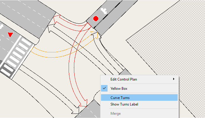
To reset the curves on all the turns in a node using default curve parameters, use the automatic curve option by selecting the Curve Turns option in the context menu for the node. Aimsun Next will automatically regenerate the curves for all the turns in the selected node. This will take into account the entrance and exit angles of the sections when generating the curves and hence should be used if the section geometry has been edited since the node was created.
Stop Lines
Stop lines define the points where vehicles will stop if they are instructed to do so by signals or by the junction rules, or they need to stop to allow other vehicles with higher priority at the junction to pass through it.
Vehicles which are approaching a stop line will check the trajectory and speed of the other vehicles with higher priority and will then make the appropriate corrections to their own speed to avoid collisions. Check the Gap-Acceptance Model in microscopic simulations and in mesoscopic simulations for more information on the behavior.
Editing Stop Lines
By default, when creating a turn, Aimsun Next will place a stop line at the end of the entry section where vehicles come to a halt. Where turn paths cross, additional stop lines might be required to mark where vehicles can enter the junction area, then wait in it, usually immediately before the conflict area. Vehicles will now wait in the junction between the end of the road section and the stop line, or between the last conflict area and the stop line if there are multiple conflicts.
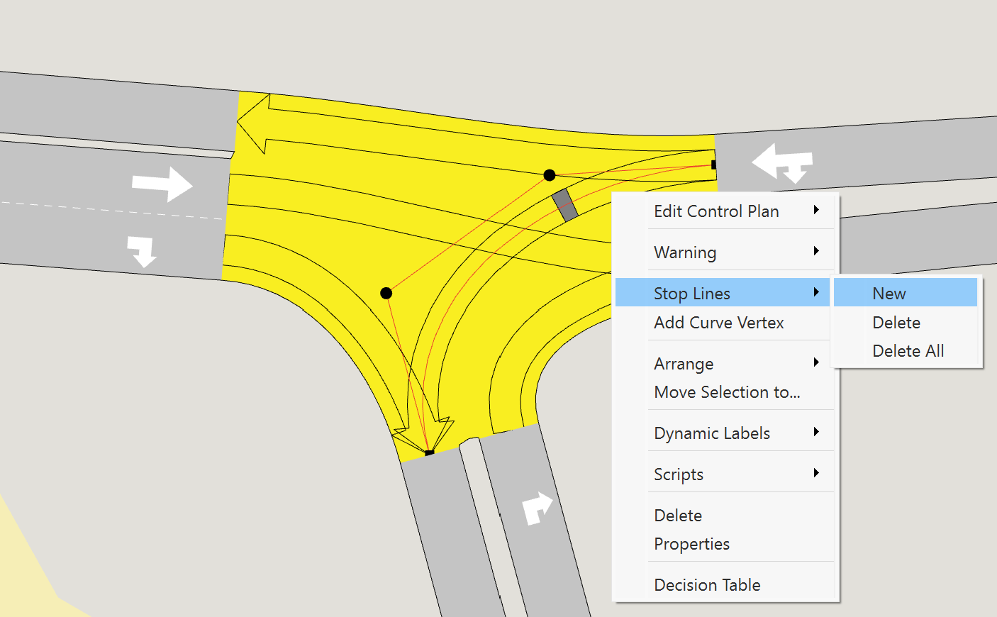
To create a new stop line on a turn, select the turn and choose New from the Stop Lines option in the context menu. If this is the first stop line added, it will substitute for the default one at the end of the origin section.
Stop lines can also be created from the node editor.
To remove a stop line, select the turn, place the cursor over the stop line and choose Delete from the Stop Lines option in the context menu. The Remove All option removes all additional stop lines and reverts to the default option (stop line on the section).
Stop lines can be moved by clicking within the stop line area and sliding the stop line along the curve.
Additional stop lines are only taken into account in microscopic simulations.
Stop Lines and Pedestrian Crossings
The interaction between Stop Lines and Pedestrian Crossings is described in the Pedestrian Crossing Editor, and it depends on how the parameter Vehicles Yield to Vehicles Before Pedestrian Crossing is set.
Node Editor
Double click on a node or select the Properties option in the node context menu to open its editor. The node editor is divided in four tabs:
- Main: Create and edit turns.
- Signal Groups: Create signal groups and assign turns to them.
- Yield: To edit priorities in conflicting turns.
- Attributes: Display and edit the additional node attributes.
- Detailed View: A plot of the turning movements.
Main Tab 
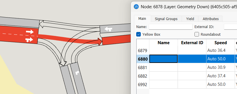
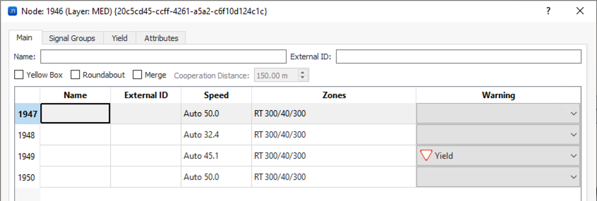
The main tab edits the node name, external ID, the Yellow Box checkbox for vehicles to keep the node clear, the Roundabout checkbox to activate the lane selection model for roundabouts when the vehicle enters the entry turn Look-Ahead Distance (the lane selection depends on the angle formed by the entry and the exit points), and the Merge checkbox to activate the merge model for connections that share the destination lane.
It also contains the turns table and the access to the editor of each turn. In this table, for each turn, you can set the Name, External Id, and Warning (Yield, Stop or RTOR). This warning can also be defined from the turn context menu. When a node is selected and its turns are visible, the turns are color coded so their priority can be viewed without opening the node editor.
- Turns which have priority are colored black.
- Turns which have to yield are colored orange.
- Turns which have to stop or are Ltor or Rtor are colored red.
The turn speed, yellow box behavior and zones are listed as well, and can be modified inside the turn editor.
Yellow Box Behavior 
If a junction is marked as yellow box, then a vehicle will only enter a turn of that junction if there is space in the next road section to exit the turn or if the preceding vehicle in the turn or next link is moving faster than a threshold speed of 15 km/h. This stops vehicles from queueing in the junction and ensures to a certain degree that it remains clear. A node can also be set as yellow box from its context menu.
Yellow Box Junction and Stop Lines 
A stop line will though modify the effect of the yellow box: it defines where vehicles can enter the node and queue inside it.
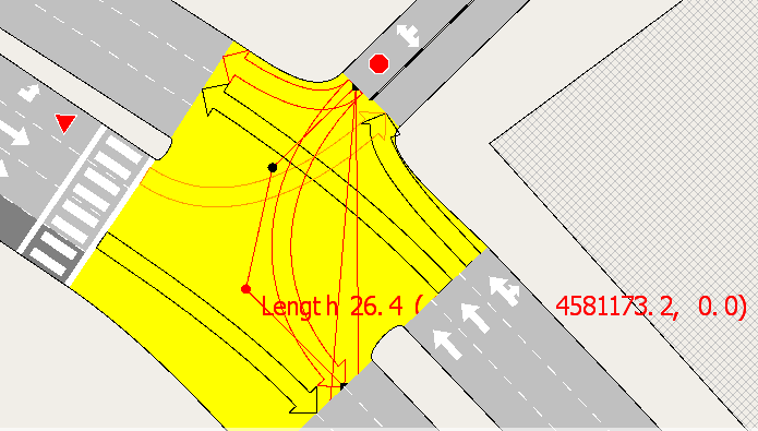
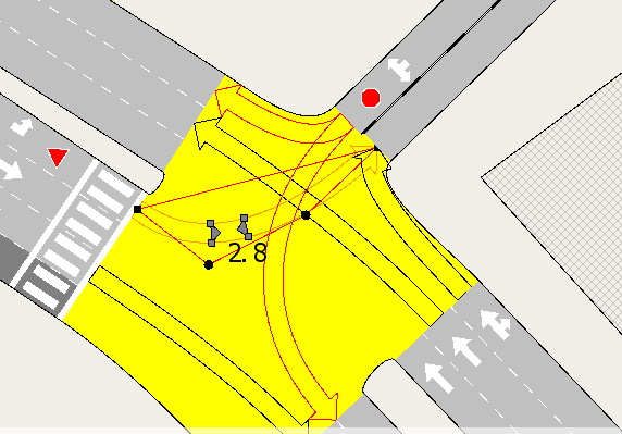
In a yellow box junction, the size of the queueing area can be adjusted by dragging the edge of the stop line and configuring the size of the queueing area. These buffers are only considered if the junction is a yellow box. In the image below, vehicles are allowed to queue in the area between the two triangles. If the stop line buffer is not created, the queueing space would be between the end of the origin section and the stop line.
Turn Data Editing
From the Node editor Main tab, select a turn in the turn table; which will then be drawn using the primary mark color in the active 2D view. Double click on the table or press Edit Turn to switch to the turn editor within the node editor. Show All Turns brings back the turn table. Information for a single turn is displayed in four different tabs:
Turn Main Tab
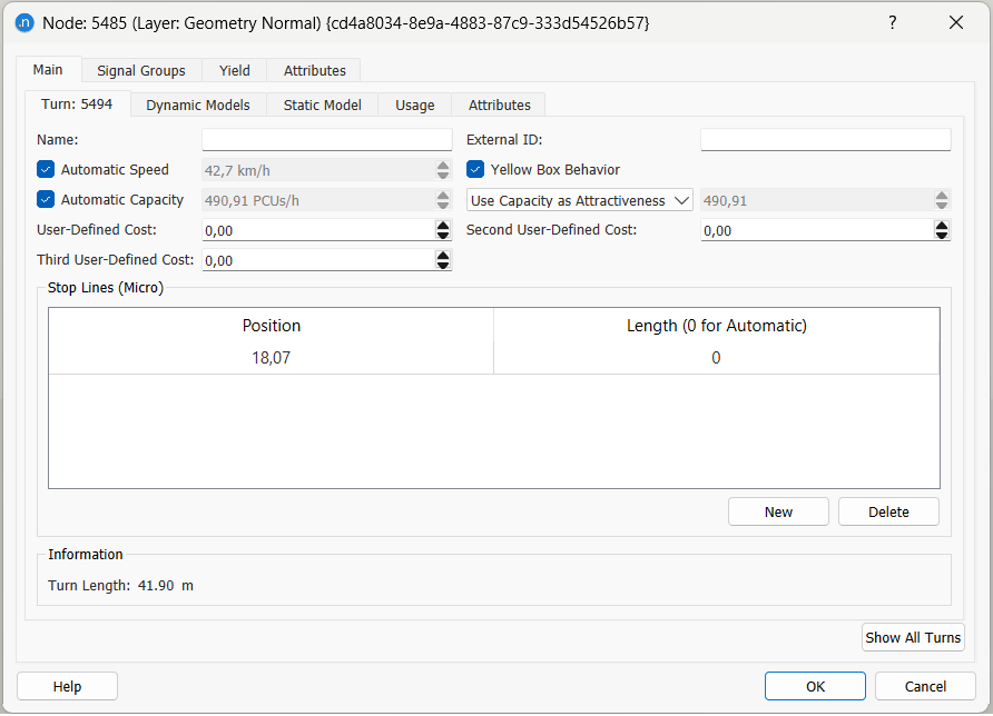
The main tab is used to edit:
- The turn name and external ID
- The turn speed, automatically calculated or set by the user
- Whether the turn applies the Yellow Box model if the Yellow Box is active for this node
- The turn capacity, automatically calculated or set by the user
- The attractiveness value for the turn and the section leading into it - this value is used in the path costs calculations, and can be set to be equal to the capacity of the turn or to a selected value
- User defined costs
- The stop lines defined for the turn with their position and length
Turn Automatic Capacity
The automatic turn capacity value is calculated from the flow capacity of the destination section, the number of lanes used in the turn and how those lanes are used across all turns in the node. The algorithms for assessing turn capacity are described in the Dynamic Traffic Assignment Theory Section.
Turn Speed
The turn speed is the speed limit the vehicle will consider when traveling through the turn. Depending on the characteristics of the driver and local congestion, and depending on the simulation parameters, drivers will calculate their desired speed (refer to Micro or Meso behavioral model for more details). Assuming the turn speed is lower than its origin section, and that the vehicle's desired speed is higher than the speed limits, the vehicle driving through the origin section will start to decelerate while approaching the turn in order to reach its turn speed at the end of the section. The turn speed is maintained during the turn and, when entering the next section, the vehicle will start to accelerate again according to its desired speed for this section.
The default turn speed is an automatic calculation for curved and straight turns; if set to automatic, the speed will be evaluated and automatically updated whenever the origin section, destination section or the turn geometry change. The formula for setting the automatic speed is described in the Node Defaults section.
Turn Dynamic Models Tab
The cost functions for the dynamic simulator route choice calculations are selected here. Refer to the Dynamic Traffic Assignment Algorithms section for more information on the role of cost functions in micro and mesoscopic simulations.
Also the look-ahead distances and yield parameters for both microscopic and mesoscopic simulators are specified here.
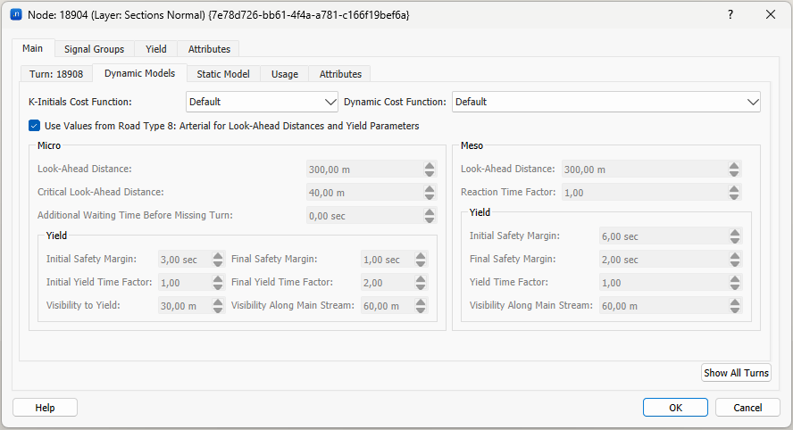
The microscopic simulator parameters are:
- Look-Ahead: The distance to the start of lane changing zone 2.
- Critical Look-Ahead: The distance to the start of lane changing zone 3.
-
Additional Waiting Time Before Missing Turn: In zone 3, vehicles try to reach their destination lane, slowing to a stop if needed. If these stopped vehicles do not manage to reach their destination lane, they will continue in their current lane and fail to make their turn after having waited their Maximum Yield Time plus the additional waiting time before making the wrong turn. This parameter can take values between -3600 and 3600. A negative value will reduce the original waiting time based on the yield calculations to a maximum of 0 seconds.
-
-
Initial Safety Margin: This is the safety gap, expressed in seconds, required between a passing yielding vehicle and the next priority vehicle. This gap is used when the yielding vehicle has just arrived at the yield sign.
-
Final Safety Margin: This is the safety gap, expressed in seconds, required between a passing yielding vehicle and the next priority vehicle. This gap is used when the yielding vehicle has now been waiting for a time at the yield sign.
-
Initial GW Time Factor: Multiplied by the giveWayTime of the vehicle, this factor determines when the gap required by the vehicle starts to decrease linearly from the maximumGap value.
-
Final GW Time Factor: Multiplied by the giveWayTime of the vehicle, this factor determines when the gap required by the vehicle has reached the minimumGap value.
-
Visibility to Yield: When a vehicle is approaching a junction on a section where there is a Yield or Yield sign at the end; the gap-acceptance model is applied. It will start to be applied whenever the distance from the vehicle to the end of the section is less than this visibility distance (in meters). This distance can extend into the preceding section or even sections. It is also applied with respect to pedestrian crossings to give a distance from the pedestrian crossing that a vehicle can see whether or not the crossing is being used.
-
Visibility along Main Stream: This is the distance in the opposing section which the yielding vehicle can see and hence take into account vehicles which have priority over it.
-
The mesoscopic simulator parameters are:
- Look-Ahead Distance.
- Reaction Time Factor. The Reaction Time Factor is a parameter that can be found in the Road Type editor, Section Parameters tab and also in the Section editor, Dynamic Models tab. The model usage of the Reaction Time Factor are detailed in the Mesoscopic Traffic Modelling section.
- Yield Parameters.
Static Models Tab
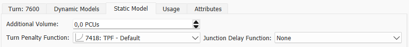
The macroscopic functions and parameters to be used in the macroscopic model are found here.
When the TPF is set to TPF - Default, a function included in the template and assigned by default to all turns by Road Type parameters inheritance when using the template as a starting point, this returns the free-flow travel time to take the turn. When it is set to "None", this returns a zero cost.
When the JDF is set to "None", this returns a zero cost.
Turn Time Series Tab
The data collected in a simulation (counts, flows, delay time ...) is plotted as a time series here.
Turn Attributes Tab
All the additional turn attributes including the ones generated after a dynamic simulation or a static traffic assignment as output will be listed here.
Signal Groups Tab
The Signal Groups tab manages the sets of turn movements associated with each traffic light. Groups can be created and deleted using the New and Delete buttons.
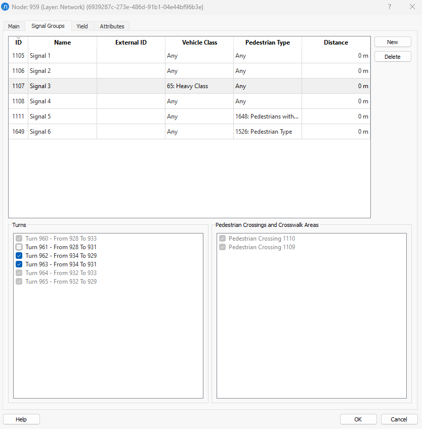
The attributes for signal group are:
- The turn movements selected from the list of turns at the node. A turn can only be included in one signal group (unless applying different signal groups for different vehicle classes at the same turn). That is, if a turn is included in a signal group for vehicle class 'Any', it will be grayed out and not available for selection in any other signal group. But, for example, if a turn is included in a signal group defined for vehicle class 'Transit Vehicles', then another signal group defined for the 'rest of vehicle classes' can be defined and include this turn again. The same type of management applies in microscopic simulations for pedestrian crossings and pedestrian types: a pedestrian crossing or crosswalk area will only be included in a signal group, unless it is pedestrian type specific. Refer to Pedestrian Crossing Signal Groups for a detailed description.
- The vehicle class this signal group affects to ('Any' for all vehicle classes).
- The pedestrian type this signal group affects to ('Any' for all pedestrian types).
- The distance upstream from the end of the section, where the vehicles affected by this signal group will stop.
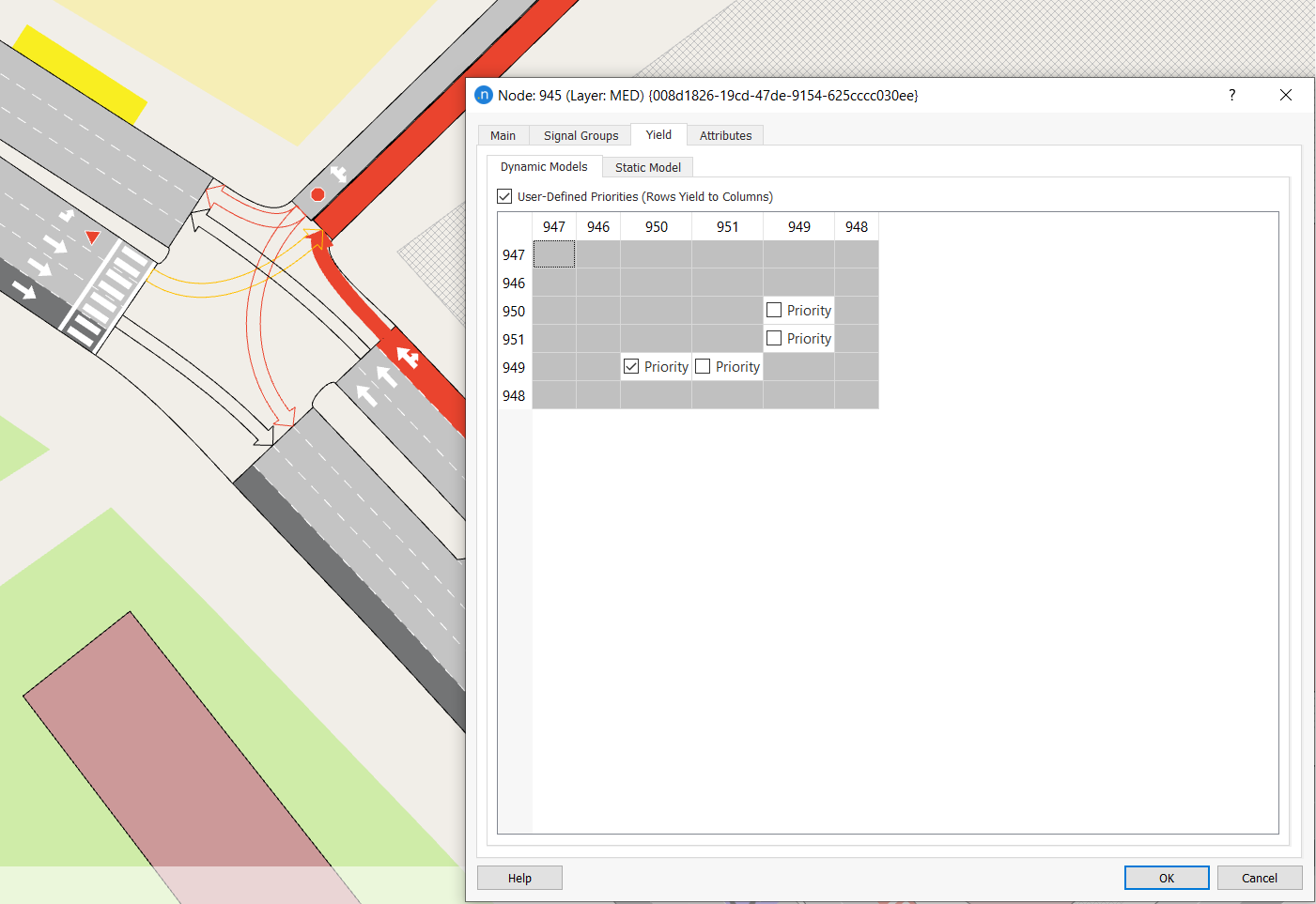
Yield tab
For the turn movements with a warning sign defined (Yield or Stop sign) the relative turn priorities are defined in the Yield Tab.
The Yield Tab shows a tab for the Dynamic Simulators in which each cell corresponds to a pair of movements at the node. If both turn movements have a yield or stop sign, the cell has a "Priority" checkbox that defines which has right of way over the other. If only one turn movement has a yield or stop sign, the other has right of way over it by default.
If the option User Defined Priorities (Rows Yield to Columns) is not checked, the table is not editable. In this case, Aimsun Next will assign the relative priority between turns with a yield or stop sign depending on the rule of the road. If the rule of the road is set to Right, then priority to the right is assigned; if the rule of the road is set to Left, then priority to the left is assigned. When this default behavior is applied, no additional preference is made based on whether the sign is a yield or a stop.
If this rule has to be overridden, check the option User Defined Priorities (Rows Yield to Columns) and check the cells in which the turn movement of the row has to yield to the turn movement of the column.
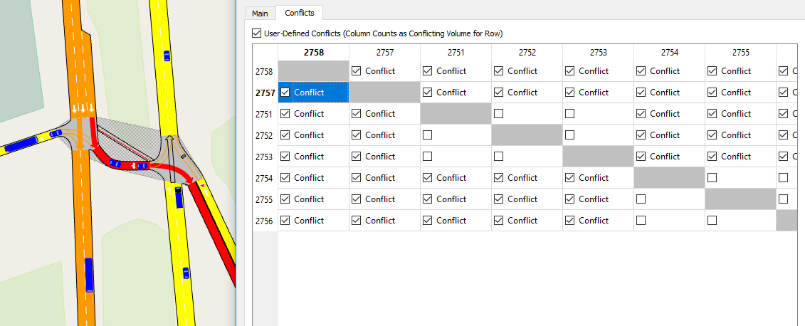
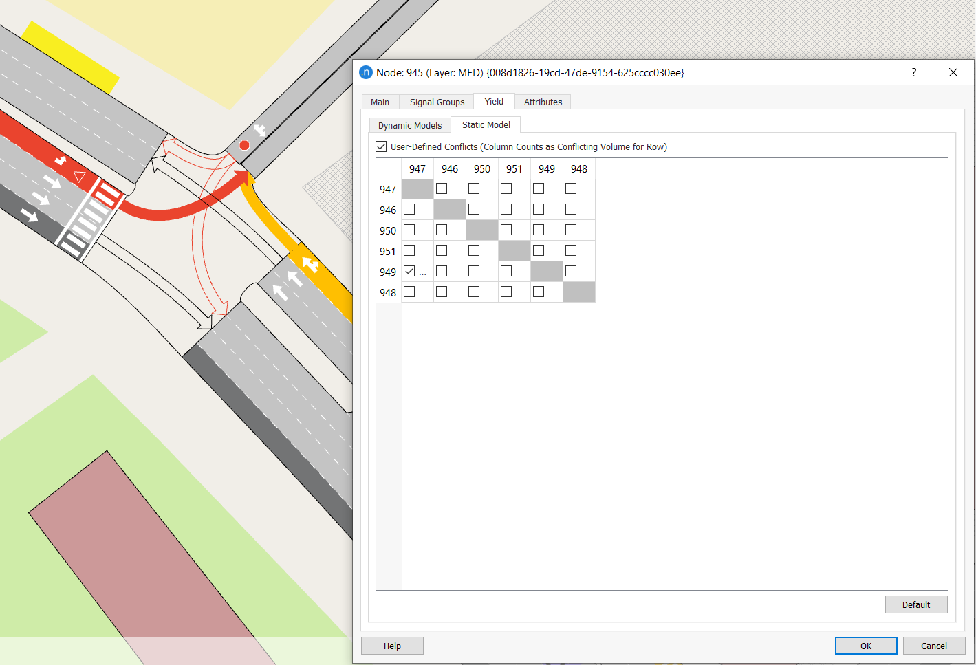
Static Model Conflicts tab
For Macroscopic Junction Delay functions, the geometric conflicts between turns is calculated automatically, but it is also possible to specify conflicts manually. The User-Defined Conflicts table specifies which 'column' turns volume should count as in conflict with the 'row' turn. Note that only the turns are specified; the conflicting volume will always be automatically calculated based on the corresponding conflict turns.
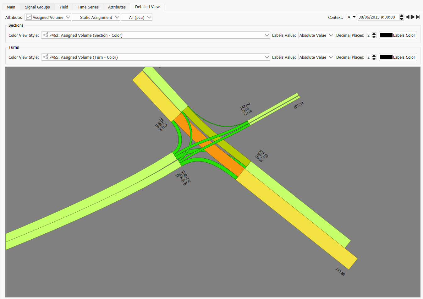
Detailed View Tab
The detailed view is designed to improve visualization of nodes when view modes are used that show data through widths on road sections, offering a more elegant view that what can be achieved with the standard view modes.
In the node detailed view, the display of the junction is improved by adjusting the display of the turns, first to manage overlaps with adjusted curves which offset the origin and destination of the turn, and second to rationalize the widths of the lines to match the width displayed for the road. In the detailed view, the label and the color View Style can by modified independently for sections and turns. Detailed node views are only available to view assigned volume, count, and flow time series data.
Advanced Node Editing 
The Advanced Editor is available from the node context menu, and it is used to fine tune the Connections and Conflicts in the node.
Connections
Although, from the modeler’s point of view, the network created with Aimsun Next consists of nodes and sections, before execution, Aimsun Next will convert these into more abstract simulation entities. Section entities correspond to lanes, while turn entities, described as connections below, are created from turns within the nodes and connect one lane in the origin section with one lane in the destination section. Vehicles therefore move along this network of linked entities according to their driver behavior model. Connections describe how a vehicle within a turn movement moves from one section entity to another. In other words it accounts for the lane choice in the destination section for the vehicle.
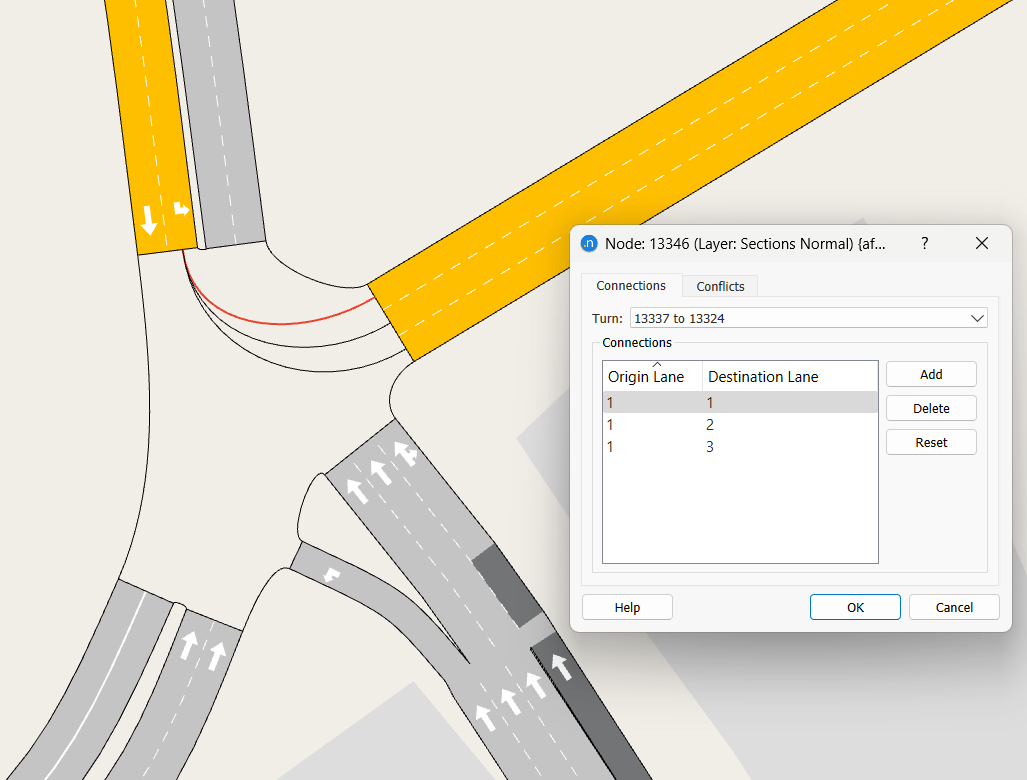
Aimsun Next uses it own internal heuristic processes to create default connections and conflict zones between the connections when the turns of a node are created. In some cases however, it might be necessary to fine tune those default definitions. The Advanced Editor, accessible from the node’s context menu, contains the connections tab folder with all the editing options. The turn combo box is used to select which of the turns in the current node should be edited. The Add button allows a new lanes connection to be added to the existing turn, while the Delete button removes the currently selected connection. The Reset button resets the connections to the default settings.
Conflicts
A conflict occurs where the connections within a node overlap and vehicles therefore have to adjust their speed or wait for a gap in the traffic flow with higher priority. A conflict zone represents an area in which a vehicle in one connection would block the progress of a vehicle in another. For dynamic simulations, conflict zones are evaluated between specific vehicles, therefore editing a conflict zone has no direct effect on the costs computed by the default static assignment Junction Delay Functions (which by default only account for whether the turns intersect or not). Within the dynamic modeling process, when a vehicle has entered the conflict zone, a vehicle from another connection cannot enter the conflict zone until the vehicle from the other turn entity has left it. The default conflict zones are calculated automatically by Aimsun Next for conflicting turn entities (connections) and can be edited if required, using the Advanced Editor from the node context menu.
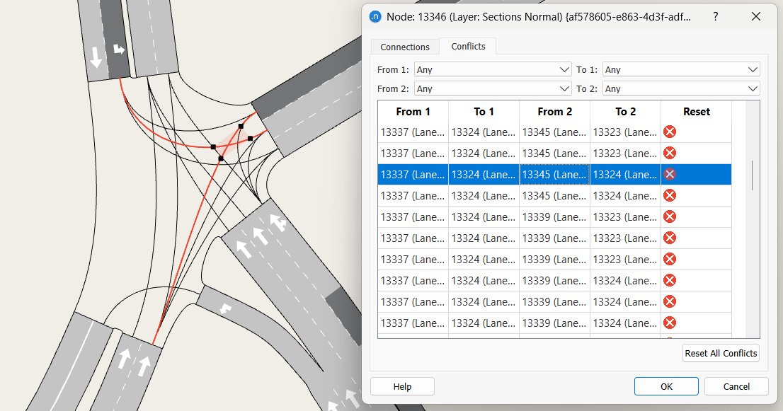
In the Conflicts tab, there is a list of all the conflicts that occur in the selected node. A conflict can be selected either by selecting it in the table, or by clicking on the intersection of the connections in the 2D view. The conflict zone boundaries (the square vertexes) can be moved by selecting and dragging them along their connection to redefine the boundaries of the conflict zone. Clicking on the Reset cell for a particular conflict resets the conflict boundaries to the default positions. All conflicts can be reset to the default positions at once by clicking the Reset All Conflicts button.
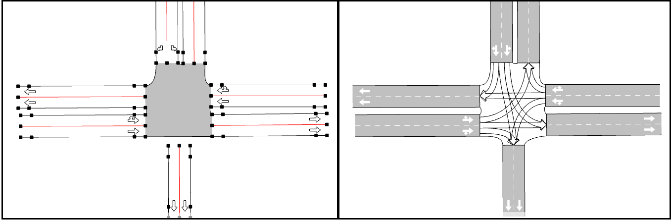
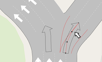
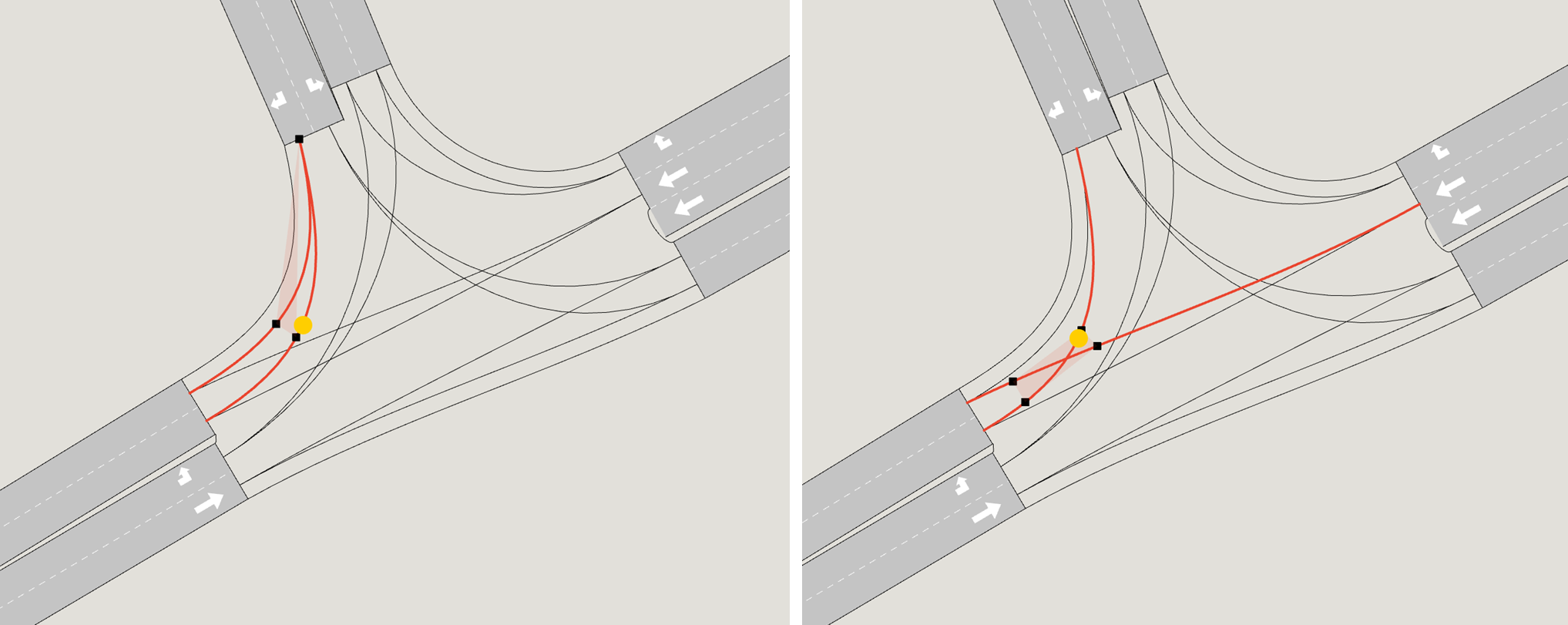
As shown below, a vehicle can be in more than one conflict zone at any one time. In this case, in the left-hand image, the two connections from the North to the West are shown. A vehicle can not leave the North entry section to go to lane 1 while another vehicle going to lane 2 is in the conflict zone. In this case, the conflict zone is between connections in the same turn. In the right hand image, the conflict zone is between connections from two turns and shows where vehicles interact. A vehicle occupying the space marked in yellow would be assessed in both these conflict zones.
Supernodes
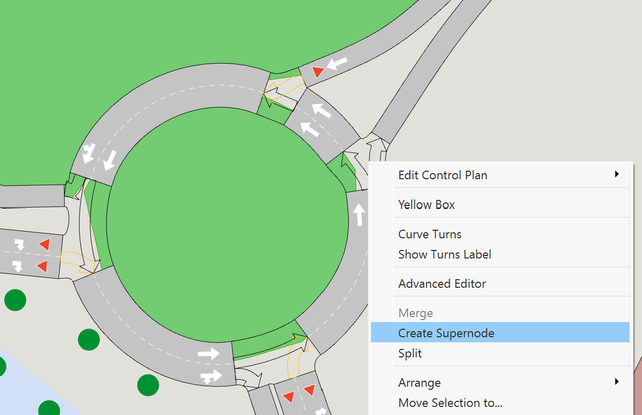
Supernodes are used to represent situations in which it is not possible to model the cost of traversing sections and turns using the sum of the individual components; i.e. when the cost of traversing the set of sections and turns is heavily dependent on the movement through them such as at a roundabout, a staggered crossroads, or at a complex junction. They are usually used in macroscopic models only. It replaces the cost of the set of turns through the junction with the full cost of each possible movement through the supernode. To do this, the user must set TPFs and JDFs (if applicable) which are adapted for supernodes in the static tab. A Supernode is created by selecting one or more nodes, right clicking on one of the nodes and selecting the Create Supernode option in the context menu.
Double clicking on the supernode in the view, or selecting the supernode and accessing the Properties through the context menu opens its editor.
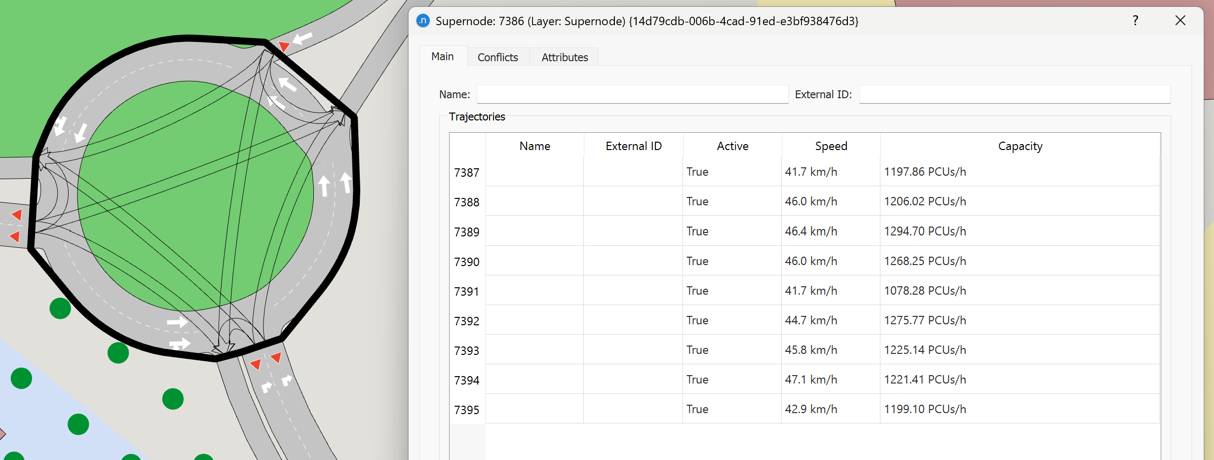
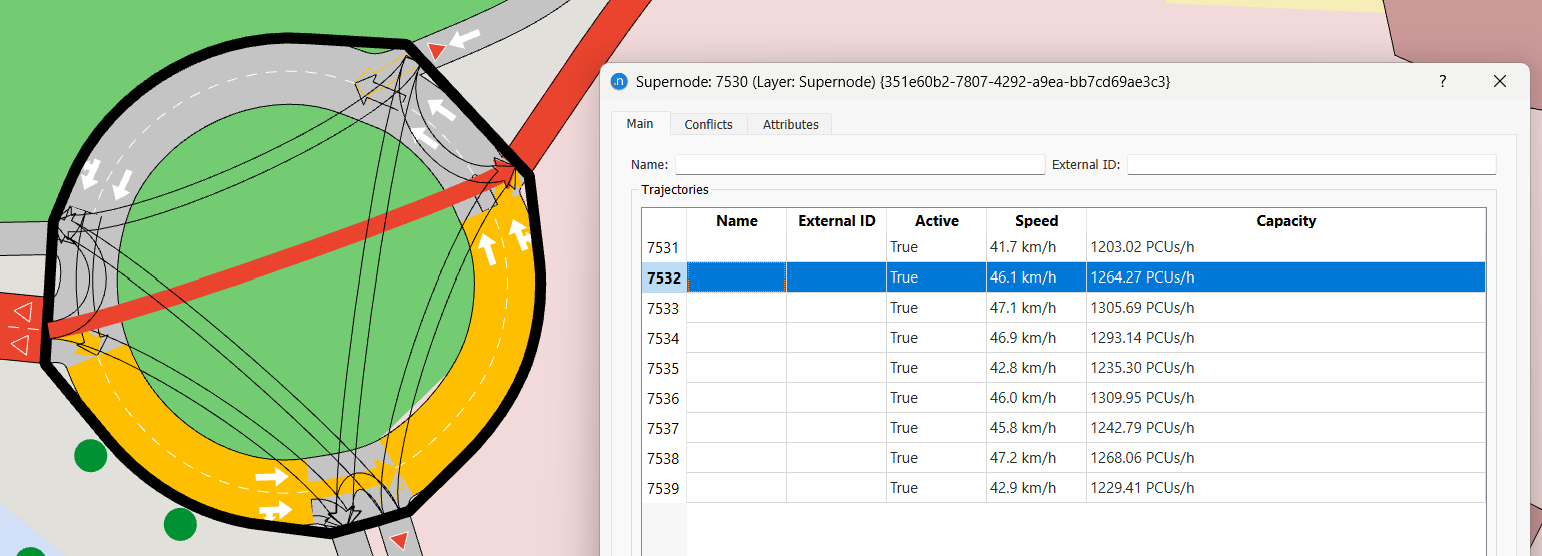
Supernode Main Tab
The main tab is used to edit the supernode name and external ID and contains a table with all the trajectories formed by the turns within the Supernode. Double click on a trajectory, or click on the Edit Trajectory button once the trajectory is selected in the table, to edit the attributes of that trajectory. Selecting the Show All Trajectories option switches back to show the list of trajectories.
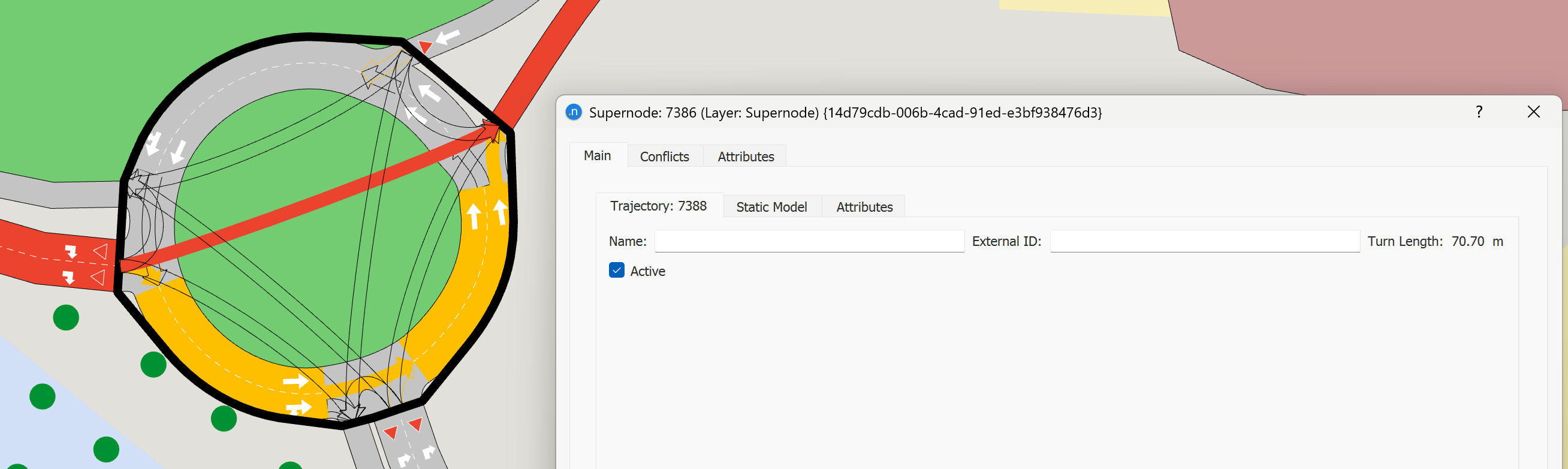
The trajectory editor within the supernode editor contains several tab folders. In the general one, the length is given as information and the trajectory name and external ID are editable, together with the checkbox setting whether the trajectory is Active or not, that is, whether it can be used in the supernode or it is not available.
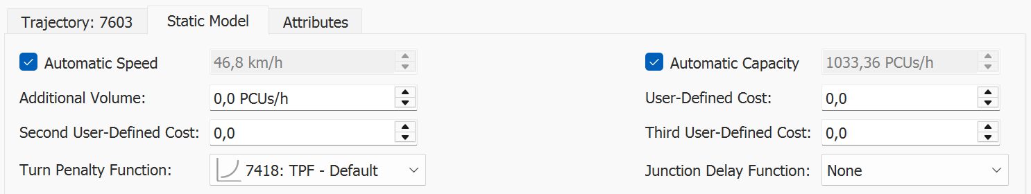
Static Model Subtab
To edit the macroscopic functions and the parameters for a supernode trajectory, switch to the Static Model subtab within the trajectory editor. The values for speed and capacity can be set as automatic and will then be calculated from the junction geometry, otherwise they can be set by the modeler. The functions are selected from the list of TPF and JDF functions in the model and their parameters are the same as those in the macroscopic model for single nodes. The user must select a TPF and JDF that has been adapted to use it for a supernode trajectory.
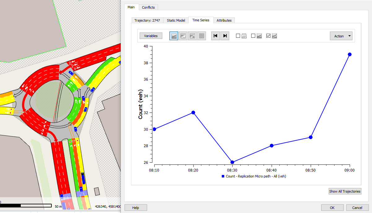
Time Series Subtab
The data collected in a simulation for the Supernode (i.e. counts, flows, delay time ...) is plotted as a Time Series or displayed as a table.
Supernode Conflicts Tab
In the Conflicts tab, the Supernode Trajectories that are considered to be conflicting geometrically are shown. The automatic conflict calculation is based on yields and stops in the node. If required, the automatic conflict definition can be overridden by the modeler. The conflict definitions are taken into account by the Junction Delay functions.