Road Types
Road Types allow the classification of sections and bulk editing of a set of sections with the Road Type Editor. They are created using the Project menu (either from the menu bar or from the Project Window) and are located in the Infrastructure main folder. All the common operations (rename, remove, and properties) are available for the Road Types by using their context menu. When removing a Road Type, the sections belonging to it are not removed, they are associated with the default Road Type instead. The default Road Type can be chosen at any time by accessing the context menu for the new default Road Type and clicking on the Set as Default option.
Road Type Editor
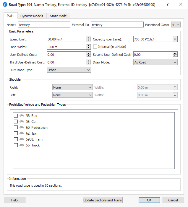
When the editor is open (see figure below), it shows, in the 2D views, all the sections that belong to this type in the primary mark color (red by default) as well as showing this number of sections in the Information part of the editor.
Main tab
-
Functional Class: The classification of the road type according to the service it is intended to provide. Aimsun Next will use this information to hide low functional class sections when the zoom level is very high, revealing more details as the user zooms in. There are several possible classification schemes:
- The Federal Highway Administration defines three: 1 for Arterial, 2 for Collector and 3 for Local roads.
- Navteq defines five: 1 for high volume and maximum speed roads to 5 for low volume roads.
-
Speed Limit, Capacity (per Lane), Lane Width, User Defined Cost, Second User Defined Cost, and Third User Defined Cost. These are explained in detail in the Section Editor manual section.
-
Draw mode: Sets the way sections belonging to this road type will be drawn. The options are:
- As Road: The default option.
- As Railway: Two black lines and rectangles all along the section will be drawn to look like a railway.
- As Tram Track: Two black lines inside the section will be drawn as the tram rails.
- Not Drawn: In 2D views, sections with this draw mode selected, together with their objects, will be drawn when editing but they will not be drawn while simulating. They will never be drawn in 3D views.
- Traffic Lights Only: Similar to the Not Drawn mode but, in this case, traffic lights and ramp meters will be drawn while running a simulation in 2D and in 3D views.
- Without Lanes: Similar to the As Road but without drawing lane marks.
-
Internal (in a Node): When this option is checked, sections belonging to this type will be considered as being inside a node so the whole section geometry will be taken into account when calculating the conflict areas used in a microsimulation model. Graphically, these sections will not be taken into account when calculating and drawing the node polygon. The Draw Mode can be set to Not Drawn to hide sections of this type.
-
HCM Road Type: Defines the HCM road classification to calculate the HCM Statistics. The possible values are Freeway, Multilane Highway, and Urban. The value None means that sections with this road type will be ignored in HCM Statistics calculations. Depending on each type, a different table for LoS is applied.
-
Shoulder: An annotation shoulder to place at the sides of the sections. You can select Right and/or Left and set a Width for each.
-
Prohibited Vehicle and Pedestrian Types: Sets the vehicle and pedestrian types that are not allowed on this type of road.
Dynamic Models tab
There are two classes of parameters for road types for dynamic models, those for sections and those for turns. In both cases the default values are set for both microsimulation model and mesoscopic simulation models.
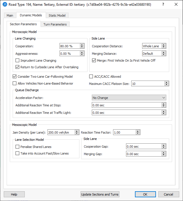
In the road type Section Parameters tab for the microscopic model:
Lane Changing: The detailed effect of these parameters is documented in the Lane Changing Model Section.
- Cooperation: This parameter denotes the percentage of upstream vehicle cooperation to create a gap for a vehicle trying to change lane.
- Aggressiveness: This parameter allows vehicles to enter short gaps followed by a relaxation period. The full process respects car following stability. The % of aggressiveness determines how short the acceptable gaps are: 100 being if the vehicle just fits in while 0 are normal gaps. Note that vehicles receiving cooperation do not enter short gaps.
- Imprudent Lane Changing: This parameter allows vehicles to enter gaps that are too short to respect the car following algorithm stability. The vehicle changing lane, or its follower, will need to brake at a rate up to twice their maximum deceleration.
- Return to Curbside Lane After Overtaking: If this option is checked, vehicles will return to the nearside lane after an overtaking maneuver, Note this is required behavior according to UK and EU driving regulations but is not universally required.
Side Lane: The detailed effect of these parameters is documented in the Ramp Merging Model Section.
- Cooperation Distance: This parameter is the distance from those side lanes that are considered to be on-ramp lanes. This is used for the specific lane-changing model applied at on-ramps, as described in On-Ramp Model section. This means that a different criterion for determining whether to consider side lanes as on-ramps or not can be applied to different parts of the network. The user can have local control of the on-ramp lane-changing model, making the calibration process easier.
- Merging Distance: This parameter sets the distance from which vehicles are allowed to merge onto the main stream within the On-Ramp model. Setting a larger distance than the Cooperation Distance has no effect. The default value corresponds to 5 times the maximum of the distance traveled in one reaction time and the length of the vehicle, which is chosen to allow the vehicle to merge onto the main carriageway before being required to slow at the end of the ramp.
- Merge: First Vehicle On is First Vehicle Off: Defines whether only the first vehicle inside the On-Ramp model is allowed to merge onto the main stream or if vehicles that are not first in line might also try to merge.
Vehicles can also be allowed to use the Two-Lane Car-Following Model in this type of road section which includes the influence of the vehicles in adjacent lanes in the car-following model.
When a vehicle is equipped with an ACC or CACC module, it will only be functional on roads whose road type allows it. To allow the activation of the ACC/CACC module tick the ACC/CACC Allowed setting. On road types with the "ACC/CACC allowed" unticked, all vehicles will behave as default Aimsun Next vehicles, using the default car-following model.
The Maximum CACC Platoon Size specifies the maximum number of consecutive CACC module equipped vehicles that will form a platoon, having smaller time gaps than normal between them .
Refer to the Adaptive Cruise Control (ACC) and Cooperative Adaptive Cruise Control (CACC) car-following section for the model details.
Queue Discharge: The detailed effect of these parameters is documented in the Vehicle Behavior Section.
- Acceleration Factor: This parameter increases or decreases the maximum acceleration of the vehicles by a factor of 0.5, No Change, 2 or 5.
- Additional Reaction Time at Stop : This is an additive local correction of the global reaction time at stop. If it is negative, it shortens the reaction time at stops in this type of road section.
- Additional Reaction Time at Traffic Light: An additive local correction of the global reaction time at traffic light. If it is negative, it shortens the reaction time to traffic light for this road type.
In the road type Section Parameters tab for the mesoscopic model:
- Jam Density: Denotes the capacity of this type of section. When a lane reaches this Jam Density, the lane is considered to be full and no more vehicles can enter until the first vehicle in the lane leaves.
-
Reaction Time Factor: This is a local parameter for the global vehicle reaction time. It provides more flexibility in the calibration process by allowing changes the vehicle reaction time. Although in general this parameter will be set to 1, it can be used to calibrate extreme situations; for example:
- Sections with a high slope.
- Sections with a sharp bend to left or to right.
- Other situations liable to be influenced by the vehicle reaction time.
-
Lane Selection Model: There are two options:
- Penalize shared lanes: When a lane is shared by more than one turn-off from the section, it is penalized in the lane selection model.
- Take into account fast/slow lanes: Slow vehicles are biased toward using slow lanes and fast vehicles toward using the fast lanes.
-
Side Lane: There are two options:
-
Cooperation Gap: It is the amount of time (in seconds) that the mainline vehicles will force to have as headway whenever side-lane (on-ramp) merging vehicles are present. This is to facilitate the incorporation of traffic. The only vehicle that will be delayed is the vehicle on the first mainline lane adjacent to the ramp.
-
Merging Gap: It is the minimum gap that vehicles in the side lane (on-ramp) look for in order to merge into the mainline.
-
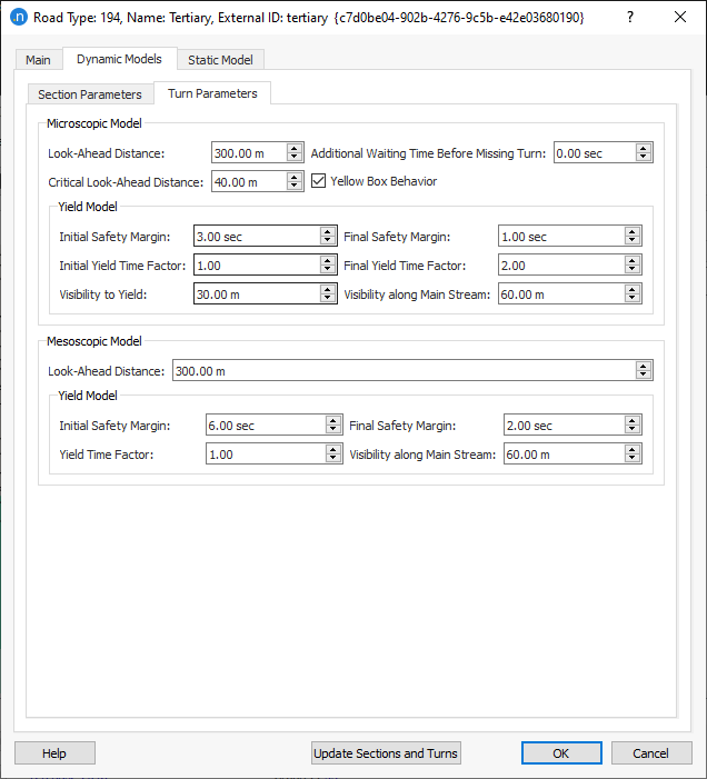
In the road type Turn Parameters tab for the microscopic model:
- The look-aheads control the lane choices made by vehicles as they approach a junction.
- Additional Waiting Time Before Missing Turn. Used in zone 3, as vehicles try to reach their destination lane. If they stop during the lane change for longer than this time they will fail to make their turn after having waited their Maximum Yield Time (Note: Yield is known as 'yield' in some territories).
- Yellow Box Behavior Vehicles waiting to enter a yellow box will be able to enter if the vehicle ahead achieves this speed while it is still clearing the box.
The yield parameters which control the time for which a vehicle will wait at a junction and the safety gap it will require to make its turn. These are documented in the Yield section of the Gap-Acceptance Model. The yield model also includes two visibility parameters: Visibility to Yield controls where a vehicle starts to consider its gap acceptance and Visibility along Main Stream controls how far it looks on the conflicting road section to observe oncoming vehicles.
In the road type Turn Parameters tab for the mesoscopic model, the parameters for the Mesoscopic Yield Model are set.
The Initial Safety Margin, Final Safety Margin, Initial Yield Time Factor, and Final Yield Time Factor control the time a vehicle will take in its assessment of moving at a turn. The Visibility along Main Stream controls how many road sections up the conflicting road will be used in this assessment.
The Look Ahead Distance in a mesoscopic model controls the forward look ahead for the vehicle across multiple road sections to determine its lane choice at the current turn.
Static Model tab
There are two classes of parameters for road types for static models, those for sections and those for turns. In both cases the default values are set for both microsimulation model and mesoscopic simulation models.
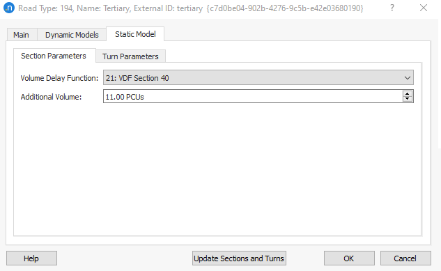
In the road type Section Parameters tab for the static model:
- The Additional Volume and Volume Delay Function for the macroscopic model.
In the road type Turn Parameters tab for the static model:
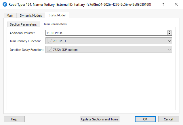
- The Turn Penalty Function, Additional Volume and Junction Delay Function for the macroscopic model.
Default Road Type
The Road Type is used as a template for newly created sections and/or turns. The Road Type marked as the Default will be set as the type for new sections and/or turns and all the values of the attributes in the road type will be copied in these new sections and/or turns. When the Road Type of a section and/or turn is changed, all the section/turn values are also changed to those defined in the new Road Type.
Use the context menu to set a Road Type as the default one. In the Project Window, the default road type will be marked in red.
It is possible to change the values of all the sections and Turns of a particular type at once by pressing the Update Sections and Turns button. If the Update Sections and Turns button is not pressed, the changes in this editor will not affect the existing sections and turns, but will affect the sections created later and assigned to this type.