GIS Importer/Exporter
The main objective of this feature is to load GIS files (ESRI shapefiles or MapInfo files, among others) into Aimsun Next and to extract as much information as possible from them to create a traffic network. This enables you to create networks from several sources - for example an open-source GIS, such as QGIS (www.qgis.org), or a commercial product, such as ESRI.
You can also use other transportation packages as data sources, if they can export their network data into GIS files. These include, among others, Cube and TransCAD.
The ability to export information from the network geometry to GIS shapefiles is also available.
File formats available for the import/export of GIS information:
- ESRI shapefile (SHP)
- MapInfo file (MIF)
- GML (KML)
- GeoPackage (GPKG)
- GeoJSON (GEOJSON)
- Geodatabases (GDB directories) (only for import)
GIS Importer Modes
GIS data can be imported into Aimsun Next in two different ways:
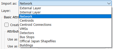
- As objects stored in the Aimsun document (Internal Layer, or Network or a specific object type from the dropdown list).
-
As an External Layer.
Importing as objects in the Aimsun document
When importing data from another format as an Internal Layer, or Network or a specific object type from the dropdown list, Aimsun objects are created and stored in the Aimsun document. The GIS files will thus no longer be used. Within this option, there are several ways to import:
- As an Internal Layer: the file is converted into lines and points.
- As a Network: the GIS network will be converted into an Aimsun Next network. A second dialog asking for extra information on attributes for the import process will appear.
- As Centroids, Centroid Connections, VMS, Detectors or Bus Stops: the file will be used to create the corresponding Aimsun objects.
- As Buildings: For each polygon on the file, an extruded polygon with the selected height will be created. The height can be either random, fixed, or can come from one of the attributes of the objects.
Importing as an External Layer
For some file formats (CAD, GIS, Raster Images) it is possible to store a reference to the file rather than storing the data in the Aimsun document. In this case, the file is imported as it is, no conversion of objects is carried out and no data is created in the Aimsun document except from the external layer itself, in which the path to the GIS file is stored. The file must therefore remain accessible to the Aimsun document, as when the user retrieves an Aimsun document that contains an external layer it will load the data from this GIS file.
Aimsun Next uses external layers to identify when the data in a drawing layer comes from an external source. This kind of layer has an Auto Retrieve property which, when toggled on, reads the external data and incorporates it into the traffic network on document retrieval - otherwise the user can load the data at any moment using the Retrieve command). On document save, only the location of the external file will be stored.
Data in an external layer cannot be edited in Aimsun Next.
Shapefile Introduction
The Shapefile spatial data format is open and published by ESRI. Shapefiles store non-topological geometry and attribute information for the spatial features in a data set. Shapefiles can support point, line, and area features. The shapefile concept includes as many as five file types with specific file extensions. These files should be stored in the same workspace as the Aimsun document.
Shapefile file extensions and their function:
- SHP: the feature geometry.
- SHX: an index to the feature geometry.
- DBF: the associated dBASE file containing attribute information.
- SBN and SBX: a spatial index of the features.
- AIN and AIH: an attribute index of active fields in a table or a theme’s attribute table.
When a shapefile is imported to create data in the Aimsun Next document, the importer will use the feature geometry (shp) to create one Aimsun object for each object found in the shapefile. It will then use the attribute information to set the Aimsun object attributes.
For example: if the option to create a network from a shapefile is selected, the importer will create a section for each object in the shapefile. The geometry (must be either a line or polyline) will be used as the center line of each section. The attribute values will be used to set the number of lanes, capacity, road type, etc.
GIS File Units
Aimsun Next uses the metric system internally. When importing a GIS file, its coordinates are transformed to meters if they are in feet or latitude and longitude. In the second case, a conversion to WGS84 UTM coordinates is used. For this reason, if coordinates are not in meters, it is important to set correctly the UTM zone or WKT/EPSG reference for the model coordinate system before importing. This can be done when starting a new project, or from the project properties.
Data Requirements
The amount and quality of the data found in the GIS file will determine the quality of the imported data. If no number of lanes information is present, the importer will create single lane sections; if no speed information is found, a default speed will be set (using the active road type) and so on.
Network Creation
Usually GIS data does not contain detailed traffic network geometry information. The missing information may be:
- On ramp or off ramp information: A section contains only the main lanes or, if the on/off-ramp is included, it is coded as a full lane.
- Space for the nodes: a node is coded as a point instead of as an area.
- Turn information: The section connectivity, if available, only codes "all to all" lanes turns (instead of, for example, specifying that only the left most lane is allowed to turn to section Y from section X).
The importer will automatically create the node area based on the in and out section geometry and will do its best to create the correct turn information. No on/off-ramp will be created. However, the importer can be enhanced to extract non-standard information with our Customization Services.
Customization Services
The main objective of the importer is to create a network with the highest quality and maximum amount of information. If the information is coded in a format not supported by Aimsun Next, or if extra data can be extracted from other sources of information, then the Aimsun support service (support@aimsun.com) offers customization services to enhance the importer.
These services include modification of the importer logic (to add implicit rules) and the inclusion of interfaces to other data sources such as Access or Excel files, spatial databases and files in custom data formats.
Importing a GIS File to create a network
The stages are:
- Start Aimsun Next.
- Create a new document using a template (setting the WKT/EPSG).
-
From the File menu, choose Import / GIS.
-
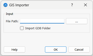
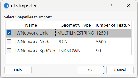
Locate the GIS file to import. When importing a GDB folder instead of a file, first check the corresponding checkbox, so that the file path dialog allows folder selection instead. In this latter case, an extra dialog will appear, where you need to select the polyline layer corresponding to the links or sections definition from the table.
-
After selecting the file or folder to be imported, the GIS File Properties dialog appears, with several settings.
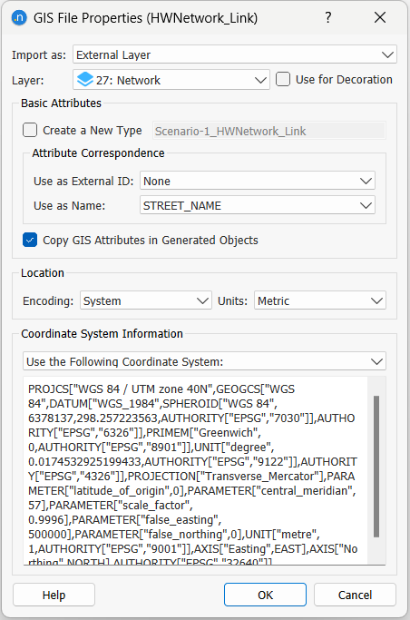
-
This dialog asks which import mode to use in the Import as combo.
- It also requests the attributes in the GIS file to use as name and external ID of the created objects. Set the attribute in the shapefile to be used as the external identifier. Aimsun Next will assign its own identifier on each imported object. The external identifier is also used to keep the identifier used in the shapefile. Set the attribute to be used as the name of each object.
- When importing data in a language not covered by the ASCII character set (i.e. Chinese, Japanese…) the correct encoding must be set.
- Set the units system which will be used in the attributes of the network (for example, speed in km/h or mph).
- Aimsun Next will look at the coordinate system of the file, which is marked in the Coordinate System Information text box. The CS will be either kept, projected or re-projected, see Imported Data and the Coordinate System.
The imported objects will be placed in a new layer whose name will be the name of the type used.
Network Importer
When choosing to Import as a Network, the network importer will extract as much information as possible from a GIS file to create an Aimsun Next network. The network importer will create a section for each polyline found in the GIS file. Then it will create the nodes using the From Node and To Node attributes. Each node will contain all the possible turns between all the sections in that node. Then it will process each turn to remove the U-Turns and to fine-tune the lanes used in each turn. It will expand the nodes from a point to an area (optional step). The last (optional) step will be the import of extra node information from another GIS file.
Only GIS files that contain lines or polylines can be used to create a network. The importer will not work with polygons, points or multi-patch files.
The dialog will ask for information about the Section Creation, how to connect these sections in Node Creation, whether the links include Centroid Connections and whether any attribute can be used to assign VDFs to the sections. All the settings filled in the Network Importer dialog will be stored and kept for later GIS imports of the same shapefile.
Section Creation
Each polyline or line found in the GIS file will be converted to a new section. Note that Aimsun Next uses metric units internally. The imported GIS file will create sections in meters. If the GIS file units were meters then the geometry in the GIS file and the center line of the sections will be the same (unless some post processing is applied such as making space for the nodes).
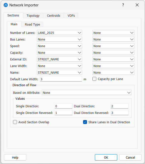
In the Sections Main tab folder, the attributes in the GIS file used to specify values for the number of lanes, speed, and capacity are selected. If no information is present for any of these attributes the following values will be used:
| Attribute | Value |
|---|---|
| Number of lanes | 1 |
| Speed | Speed from Road Type |
| Capacity | Capacity from Road Type |
If a single link in the GIS file generates sections in both directions, the attributes number of lanes, speed, and capacity can have two values. The first is for the primary section specified in the first column and the second for the reverse direction specified in the second column. If no attribute is specified in the second column, both directions are assumed to have the same value.
Single and Dual Direction
Usually the polyline in the GIS file codes a centerline of a single section, and the order of the points in the polyline determines the direction of flow. However, the importer also supports the following alternatives:
- Reversed sections: The direction of flow is the reverse of the point order.
- Dual directions: The polyline codes the separation line between two sections, one in each direction.
It is possible to combine both possibilities (inverse and dual) to give four options. The Direction of Flow parameters inform the importer how to assign the section in the right direction and if the polyline codes dual directions and hence two sections should be generated.
To do this, select the attribute that has the information and for each possibility, enter the number, character or text that identifies the correct setting. Use a non-valid entry if a setting is not permitted in the imported file.
Example: a GIS file has an attribute named DIR with these possible values:
- 0: Single Direction
- 1: Reversed Direction
- 2: Dual Direction
- 3: Dual Direction, Reversed
Enter 0 - 3 to enumerate the values in the file. If any other character is found in the file, it will be ignored.
Note that if a link is coded in the GIS file as Dual Direction it should be only be represented in the file once. For example, if a GIS link had an attribute TWOWAY indicating it was a part of a normal bi-directional road (i.e not a dual carriageway) but in the GIS file both ways were represented as separate links, then that attribute should be ignored and the individual links imported as single direction road sections.
Number of Lanes and Dual Direction
When a single polyline generates two sections, one in each direction, the GIS file might contain two attributes for the number of lanes or one. In the later case, the number of lanes attribute found in the GIS file can be considered as the sum of all the lanes in both directions or as the number of lanes for each direction. If the number of lanes is the same for both directions and is equal to the value in the attribute, fill in both columns for the number of lanes. Otherwise, activate the toggle button Share Lanes in Dual Direction to divide the number of lanes between both sections.
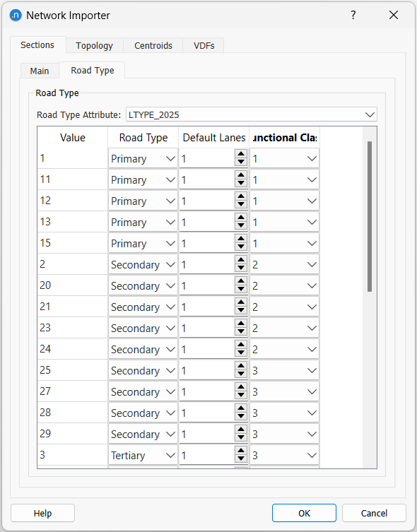
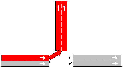
Overlapped Sections
Some shapefiles contain two overlapped centerlines for each direction of flow. The Figure below shows two links, 1 and 2, which connect two nodes, A and B. Aimsun Next can automatically move these overlapped centerlines to ensure a more representative network geometry.
This operation is activated by checking the Avoid Section Overlap option. The import process will check pairs of sections that connect opposite nodes (section 1 goes from A to B, section 2 from B to A) and will shift the sections from their original centerline.
The current Rule of the Road will be used (as set in Preferences) to determine which section will be shifted to the left of the centerline and which one will be translated to the right.
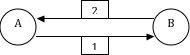
Road Types
Before importing, the road types that will be needed must be already available in the Aimsun document. These will be used to classify sections and initialize values in the sections as they are created (whenever import data is missing).
When the network importer creates the sections on the network, it is possible to use a shapefile attribute to specify the road type to be used. If no equivalence is defined, the new sections will have the default road type (as defined using the Set as Default command in the Road Type context menu).
If no value or attribute correspondence is specified in the network importer dialog for a particular section attribute then the importer will use, if possible, the values found in the road type.
If the values from the road type instead are to be be given priority, this can be done by setting the following values in the importer:
- Speed: Select None
- Capacity: Select None
- Lane Width: Leave the field blank. The road type can be set in the Network Importer dialog. If no road type is set then the default Road Type will be used.
It is possible to add a number of lanes by road type if no attribute for number of lanes is specified in the Sections Main area.
Omitting Links
Some GIS files may include links that don't need to be imported, for example a metro or train line, or the internal links in a car park. These links can be omitted from the import by setting the above mentioned road type attribute Default Lanes to zero (Don't Import). For this particular case, filling the Aimsun road type is not required.
Node Creation
If the GIS file contains topological information (in our case, how objects are connected), it can be used to create nodes where sections on the network are connected. The "From Node" and "To Node" attributes are used to create such nodes.
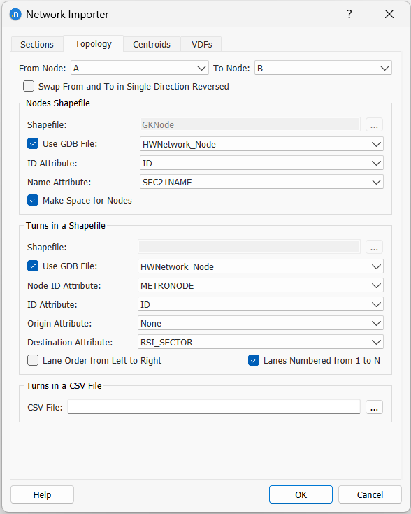
Along with the node creation, turns on the node are also created to physically connect sections to each other. As no information is available on which section is connected with which, the importer creates turns between all the sections in the node.
Turn Refinement
Aimsun Next can specify which sections are connected to which sections in a node and also which lanes are used in a turn. For example, in a right turn, maybe only the rightmost lane of a section allows such a turn and the rest of the lanes are used to go straight ahead.
The importer classifies the turns to determine if they are a U-turn, left, right or straight turn. This uses the angle between the sections that are connected before the node is expanded.
After the turn angles have been calculated and the turns classified, the importer will assign some or all of the lanes to the turn, considering other turns that start in the section, as follows:
| Turn Type | Other Turns on Sections | Lanes Used |
|---|---|---|
| Left | Straight | Left most |
| Left | None | All |
| Left | Right | Half (left most) |
| Right | Straight | Right most |
| Right | None | All |
| Right | Left | Half (right most) |
| Straight | Any | All |
Expanding the Node
If the option Make Space For Nodes is toggled on, the import process will expand the nodes from a point to an area, giving space to the turns. This step will compress the sections that are part of the node reducing each section. The compression will make the section shorter but neither the section will be removed, nor any point on it.
The compression size will depend of the number of lanes of the sections involved. The importer will use the maximum size of the section width (number of lanes * lane size) divided by 2 then, to that result, it will add 10%.
This space will ensure a correct node area for most of the cases but it will not guarantee that some sections do not overlap the node.
Adding Extra Node Information
The user can specify a second GIS file with node information. The importer creates nodes based on the "From Node" and "To Node" settings. Each node created will have as its external identifier the value of the "From Node" or "To Node" attribute.
In order to use this second GIS file the importer must match the nodes created when importing the network with the nodes found in this shapefile. The importer will ask for the attribute that contains the identifier of the node. It will also ask for the attribute that contains the name of the node.
No geometrical information will be loaded, only the attributes and its values.
Centroid Creation
Some GIS files contain centroid connections as links. In this case, Aimsun Next can automatically create the centroids and connect them to the corresponding section or node.
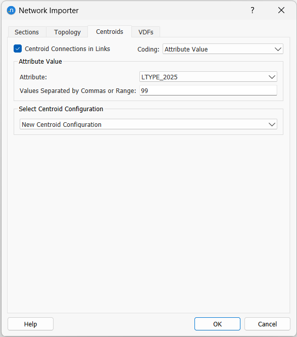
In the Centroids tab folder, enable the Centroid Connections in Links option. In the Coding combo, choose whether the importer should differentiate centroid connections from links by using a range of identifiers or by using the value(s) of an attribute.
The second option allows a list of identifiers and/or a closed range of values. The IDs are separated by commas, the range by the "-" symbol. In order to differentiate the minus symbol from a negative number, add a space after the symbol, for example: "- 9". If the second value in the range is not present, then all the range from the lower value up will be used. Example of valid inputs are:
| Range | How to write it |
|---|---|
| Links 1,2 and 3 | 1,2,3 |
| From 1 to 20 (inclusive) | 1 - 20 |
| From 20 (inclusive) | 20 - |
Centroid, VMS, Detector and Building Importer
The centroid importer creates unconnected centroids in the network. Therefore, if possible, it’s better to create centroids using the Network Importer (see Centroid Creation). This option works with shapefiles that contain points or areas:
- From points: each point will be used to create a centroid. The point will not be created.
- From areas: a centroid will be created in the center of each area. The area will not be created.
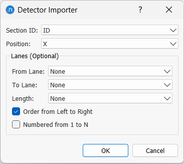
For VMS and detectors the importer asks for the section identifier (ID or External ID) in which the object resides and the offset to the section start. In addition, in the case of detectors, lanes information can be optionnally added.
The building importer will use the polygons in the shapefile to create extruded polygons (with 3D information) and with a height as specified either in an attribute of the shapefile or using a random number (between a minimum and a maximum selected by the user).
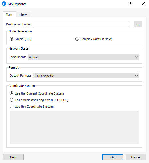
Exporting Shapefiles
Using the menu option File / Export / GIS, you can export network information to shapefiles. You must specify where to generate the files and the coordinate system to use.
Note that if the designated folder contains previous files, they will be overwritten.
Network information is exported taking into account attribute overrides and geometry configurations existent in the Network State experiment set.
You must also specify the file format to saved: SHP, MIF, KML, GPKG, or GEOJSON.
The exporter will generate files for all or selected type of objects in the Filters tab folder list:
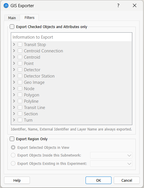
For each object type, the attributes of objects to be used or displayed in the GIS can also be selected.
If Export Region Only is checked, the objects to export are the ones selected and not the ones pertaining to the 'Network State' experiment. This allows to export different regions with the same attribute overrides.
For MapInfo, GML, and GeoJSON there will be a file for each object type, with the appropriate filename extension. In the case of GeoPackage, only one file will be exported, containing all the exported object types.
Attributes exported are covered in the next section, based on exporting to ESRI shapefiles.
Exporting to ESRI Shapefiles
Sections file
Sections will be exported to a shapefile as multiple polyline shapes with Z coordinate. The generated files are:
- sections.shp
- sections.shx
- sections.dbf
The attributes written in the DBF file are:
- id: Aimsun identifier
- name: Object name
- nb_lanes: Number of lanes
- speed: Section speed in km/h
- capacity: Section capacity in PCUs/h
- fnode: Origin node (using the Aimsun node identifier)
- tnode: Destination node (using the Aimsun node identifier)
- rd_type: Road Type identifier
Sections geo file
Additional files to provide the X and Y coordinates of the two extreme points on the axis of the section, and of the 4 extreme points to the edge of the section (entrance point at right, entrance point at left, exit point at left and exit point at right; left and right considering the section direction) are also created. These files are:
- sectionsgeo.shp
- sectionsgeo.shx
- sectionsgeo.dbf
The attributes written in the DBF file are the X and Y coordinates of the above mentioned 6 points:
- fx : X of the axis point at the entrance
- fy : Y of the axis point at the entrance
- tx : X of the axis point at the exit
- ty : Y of the axis point at the exit
- lfx : X of the left point at the entrance
- lfy : Y of the left point at the entrance
- rfx : X of the right point at the entrance
- rfy : Y of the right point at the entrance
- ltx : X of the left point at the exit
- lty : Y of the left point at the exit
- rtx : X of the right point at the exit
- rty : Y of the right point at the exit
Nodes file
Nodes will be exported to a shapefile as single point shapes with Z coordinate. The generated files are:
- nodes.shp
- nodes.shx
- nodes.dbf
The attributes written in the DBF file are:
- id: Aimsun identifier
- name: Object name
- intersection: 0 for a simple node, 1 for a complex node
Turns file
Turns will be exported to a shapefile as multiple arc shapes with Z coordinate. The generated files are:
- turns.shp
- turns.shx
- turns.dbf
The attributes written in the DBF file are:
- id: Aimsun identifier
- id_node: Aimsun node identifier
- speed: Turn speed in km/h
- sign: Warning sign: 0 for no sign, 1 for yield, 2 for stop
- fsection: Origin section (using the Aimsun section identifier)
- tsection: Destination section (using the Aimsun section identifier)
- flaneA: Origin lane, left most
- flaneB: Origin lane, right most
- tlaneA: Destination lane, left most
- tlaneB: Destination lane, right most
VMSs file
VMSs will be exported to a shapefile as single point shapes with Z coordinate. The generated files are:
- vms.shp
- vms.shx
- vms.dbf
The attributes written in the DBF file are:
- id: Aimsun identifier
- name: Object name
- section_id: Identifier of the section
- position: Position, in meters, from the entrance of the section
Meterings file
Meterings will be exported to a shapefile as single point shapes with Z coordinate. The generated files are:
- meterings.shp
- meterings.shx
- meterings.dbf
The attributes written in the DBF file are:
- id: Aimsun identifier
- name: Object name
- section_id: Identifier of the section
- position: Position, in meters, from the entrance of the section
Detectors file
Detectors will be exported to a shapefile as single point shapes with Z coordinate. The generated files are:
- detectors.shp
- detectors.shx
- detectors.dbf
The attributes written in the DBF file are:
- id: Aimsun identifier
- name: Object name
- section_id: Identifier of the section
- position: Position, in meters, from the entrance of the section
- length: Detector length in meters
- from_lane: Left most lane in where the detector is (numbered from 0 to N-1)
- to_lane: Right most lane in where the detector is (numbered from 0 to N-1)
Centroids file
Centroids will be exported to a shapefile as single point shapes with Z coordinate. The generated files are:
- centroids.shp
- centroids.shx
- centroids.dbf
The attributes written in the DBF file are:
- id: Aimsun identifier
- name: Object name
- type: Type of the centroid connections, either from, to, from_to or none
- percentages: Percentages defined for the centroid, either nothing, origin, destination, both or same
Centroid connections file
Centroids connections will be exported to a shapefile as multiple point shapes with Z coordinate. The generated files are:
- centroid_connections.shp
- centroid_connections.shx
- centroid_connections.dbf
The attributes written in the DBF file are:
- id_cent: Aimsun identifier for the centroid
- id_object: Aimsun identifier for the object connected (either a section or a node)
- obj_type: Whether the connection is to a section or to a node
- direction: whether the connection is a from (from the object to the centroid) or a to connection (to the object from the centroid)
- percentage: Percentage defined for the connection in the centroid editor
Transit stops file
Transit stops will be placed in a shapefile with one point shape with Z coordinate. The generated files are:
- bus_stops.shp
- bus_stops.shx
- bus_stops.dbf
The attributes written in the DBF file are:
- id: Aimsun identifier
- name: Object name
- section_id: Identifier of the section
- position: Position, in meters, from the entrance of the section
- length: Length, in meters
- Lane: Lane where the stop is located
- stop_type: Stop type: 0 for normal, 1 for bus bay and 2 for bus terminus
Labels file
Labels will be placed in a shapefile with one point shape with Z coordinate. The generated files are:
- labels.shp
- labels.shx
- labels.dbf
The attributes written in the DBF file are:
- id: Aimsun identifier
- name: Object name
- label: ASCII version of the label (Aimsun Next uses UNICODE strings but shapefiles do not)
Polygons file
Labels will be placed in a shapefile with multiple point shapes with Z coordinate. The generated files are:
- polygons.shp
- polygons.shx
- polygons.dbf
The attributes written in the DBF file are:
- id: Aimsun identifier
- name: Object name
- layer: Polygon’s layer
- fill: 1 if it is filled, 0 otherwise
- color: Polygon’s brush color
Types and Objects in Aimsun Next
Only relevant for Internal and External layer import.
A GIS file contains geometry and attribute information for spatial features. The geometry can be points, lines, and polygons. The information assigned to the geometry is what makes a feature type different from another one. For example, a GIS file can contain points that represent airports or cities. The difference between one type and another is the information associated with it (number of terminals in an airport or number of inhabitants in a city).
When Aimsun Next imports a GIS file it creates objects of a type based on the geometry type used in it. The issue is how to deal with the attributes. For example, when importing airports (points) and, later on, cities (also points), Aimsun Next will create a point for each new object. For the attributes, one option is to add all attributes to all points, which means a given point will have airport and city attributes but some of them, depending of the type, will be unused. The other option is to only add the relevant attributes to each point which means the point representing an airport will have airport attributes and no city attributes. This implies that different instances of the same type of objects (point) will have different sets of attributes.
The solution implemented in Aimsun Next is the extensible object model in which:
- New types can be added to the system at run time.
- New attributes can be added to any type at run time.
Following the example, Aimsun Next will create a new type, Airport, to hold all the airports. For this type, the attributes found in the GIS file will be used. In this way, Aimsun Next will know which points are airports, which ones are cities and which ones are simple points.
The new type is created as a subtype of a geometrical Aimsun Next type based on the type held in the GIS file. The GIS Importer therefore requires the name of the type to be used for the new objects.
Incompatible Types
When Aimsun Next imports a GIS file it uses the specified type name (from the GIS File Properties dialog) to create a new type or to use it if it was already present. If the type was already present then it must be compatible with the information found in the GIS file. That is:
- The geometrical type must be the same. It is not possible to use the type City for points and subsequently attempt to use it for polygons.
- The attributes of the type must be the same. In this case, we cannot first import cities creating the City type and then try to import airports using the same type (an unusual operation) as the attributes of the airports GIS file will not be present in the City type.
When types are incompatible, the importer will pop up an error dialog such as the one shown below.
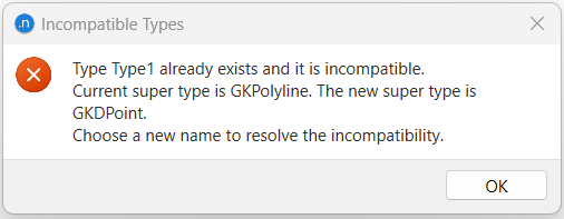
The type name is used to assign a type to each object imported. The type name must refer either to a type that doesn't exist or to the name of an already existing type that can be used by the objects that will be imported. For more information, see the point Types and Objects in Aimsun Next below.
The imported objects will be placed in a new layer whose name will be the name of the type used.