LISA Interface
LISA is a software package from SCHLOTHAUER & WAUER GmbH which is used to plan and optimize traffic signal plans for single intersections and for road networks. The LISA actuated signal controller dynamically changes signals based on the actions of vehicles passing over detector loops in the vicinity of the signalized junctions to optimize the traffic flows.
Architecture
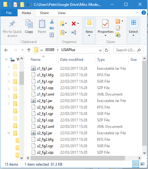
The LISA controller emulation files are created by LISA and saved in a single directory, this contains a Java ".jar" file and 5 configuration files for each controller. When the simulation is run, the LISA OML Server runs these files and uses them to emulate the LISA Controller.
Requirements
The requirements are:
- The Adaptive Control Interfaces License Extension for Aimsun Next.
- A Java Runtime Environment version 8 (1.8.0) installed on the computer running the simulation. The installer for the different operating systems can be downloaded from https://www.oracle.com/java/technologies/downloads/ under the section Java archive > Java SE 8.
Note that LISA does not need to be installed to run the simulation using the LISA signal controller, as the LISA OML Server is included in the Aimsun Next installation. However, it must be available if the modeler wants to edit the LISA control files.
Preferences and Settings
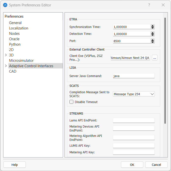
The Server Java Command, set in the System Preferences Editor, specifies how to start the Java VM that runs the LISA Emulator. If the Java VM is in the system path and will be run on the local host computer, the simple java command will suffice. In other cases, for example if the Java VM is not in the system path, or if there are multiple versions installed in the system, the command must reflect this and specify how to start the right VM, e.g. "C:\Program Files (x86)\Java\jre-1.8\bin\java.exe".
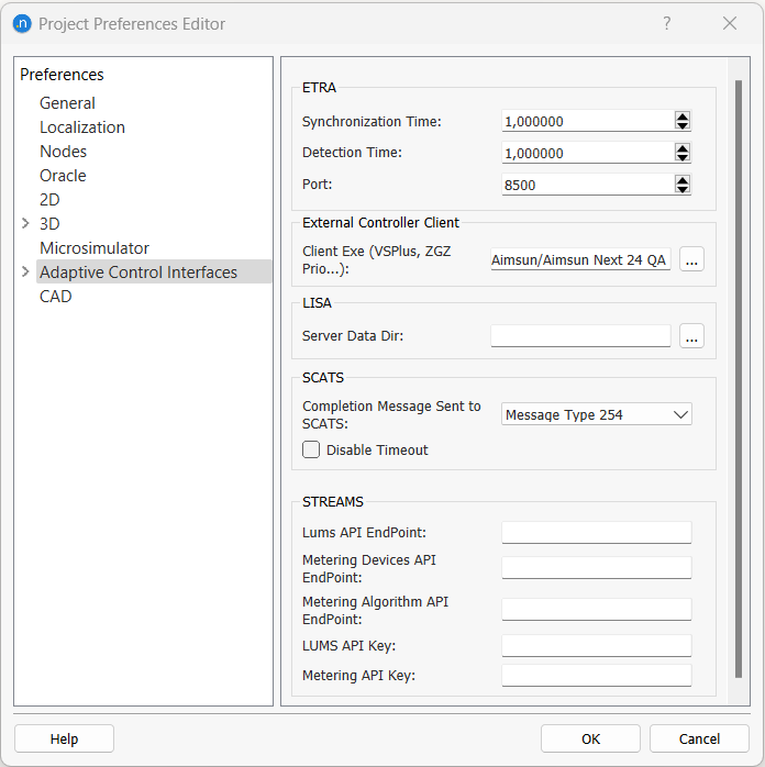
The Server Data Dir, that is, the path to the LISA emulator files folder, is set in the Project Preferences Editor. This folder is unique for all LISA controllers in the project.
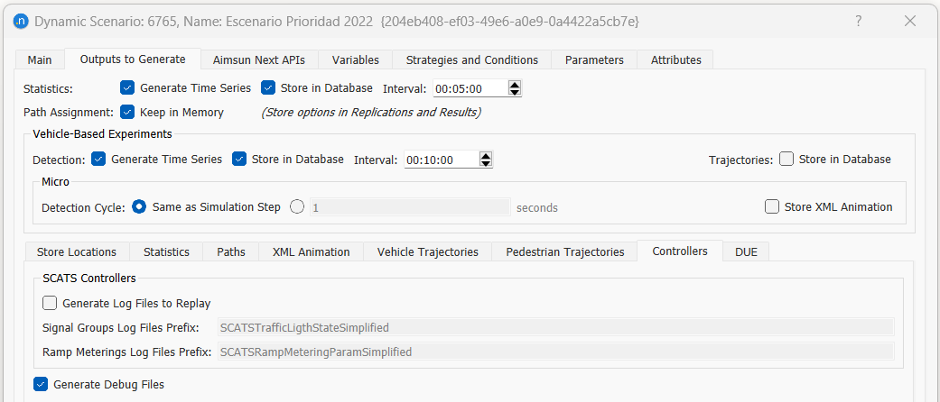
The LISA interface can be configured to produce debugging information. The option Generate Debug Files is selected in the Scenario editor, Outputs to Generate tab, Controllers subtab. When this option is active, Aimsun Next will generate log files stored in the same folder as the Aimsun Next document, named LISAPlusMessages_ID.log where ID is the LISA Controller ID in Aimsun Next.
LISA Controller Editor
The signal groups, the detectors and the pedestrian push buttons in the simulation model must be mapped to the corresponding objects in LISA. This is achieved in the Controller editor.
The Controller is created and edited using the Controller Editor. If the LISA option is selected in the main tab, the editor is configured for LISA.
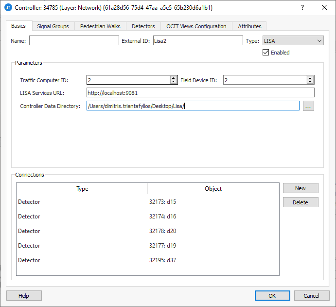
The parameters required to link to the LISA Controller Emulator are:
-
Traffic Computer ID and Field Device ID: these are LISA controller identifiers that should match those in the names of the controller emulators exported from LISA.
-
LISA Service URL: The link (computer name and port number) to the LISA OML Server. You don't need to change the default setting when using the one provided with Aimsun Next and launched automatically at the beginning of the simulation.
-
Controller Data Directory: This is the directory where the controller emulator files of each intersection (.jar, .kfg, .ov4, .sgr, .szp, .xml) and its configuration files are stored. This way you can have each intersection emulator in a different folder, which is the default when exporting from LISA, instead of having to copy all in one folder. The file names match the Traffic Computer ID and the Field Device ID of the controller for each junction and should not be changed.
The Connections box lists all the items (Nodes and Detectors) that have been linked to the Controller using the Connection Tool.
Signal Groups
The Signals Group tab is used to match the signal groups in LISA to the signal groups added to the node using the Nodes Editor. Each signal group in LISA must be matched to the equivalent group in the node.
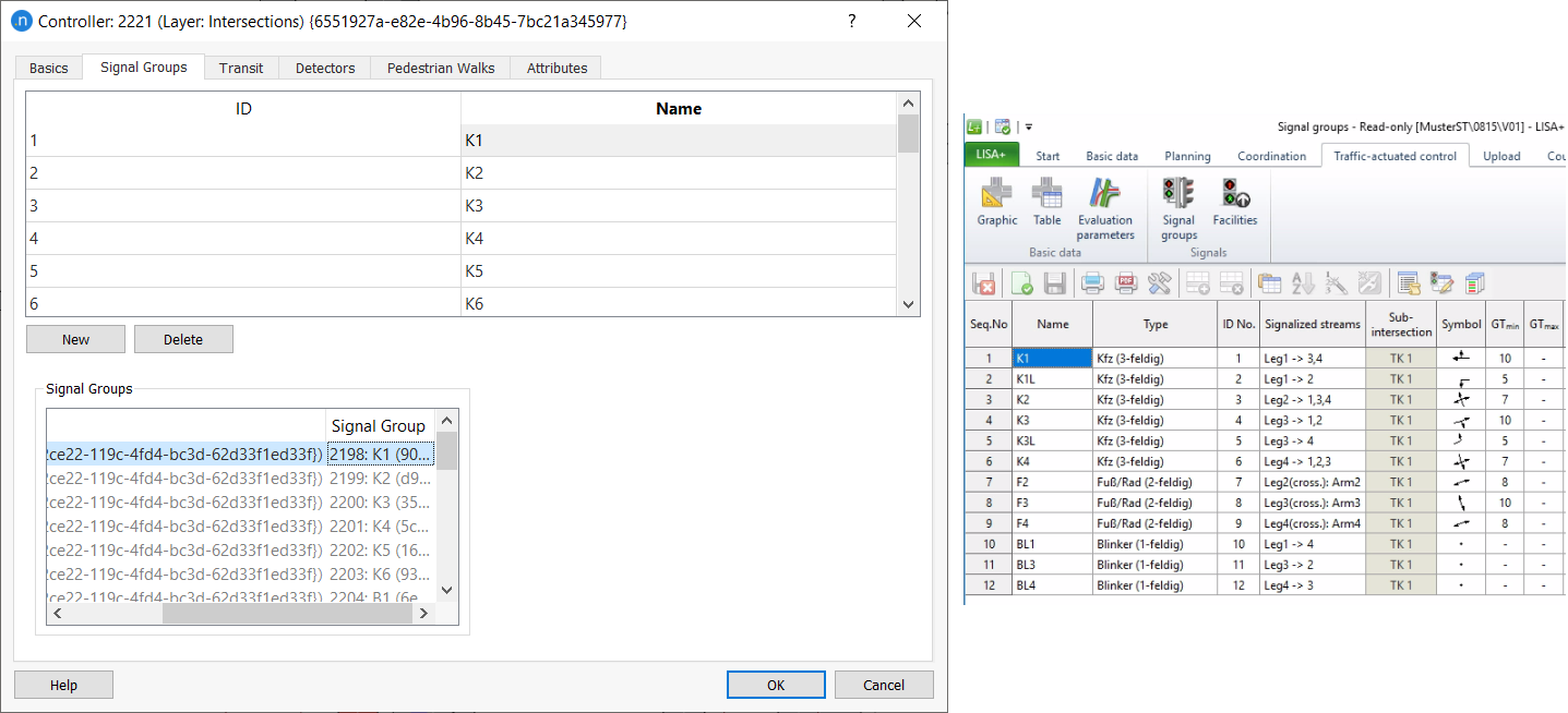
The Secondaries setting is used to make the status of a signal group follow that of another signal group when off (or even red, if Override Red State is checked). This is commonly used for protected/permitted turns, which are controlled by a green arrow during the protected stage, and then during the permitted stage by the green ball that controls the other turns from the approach.
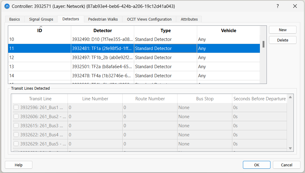
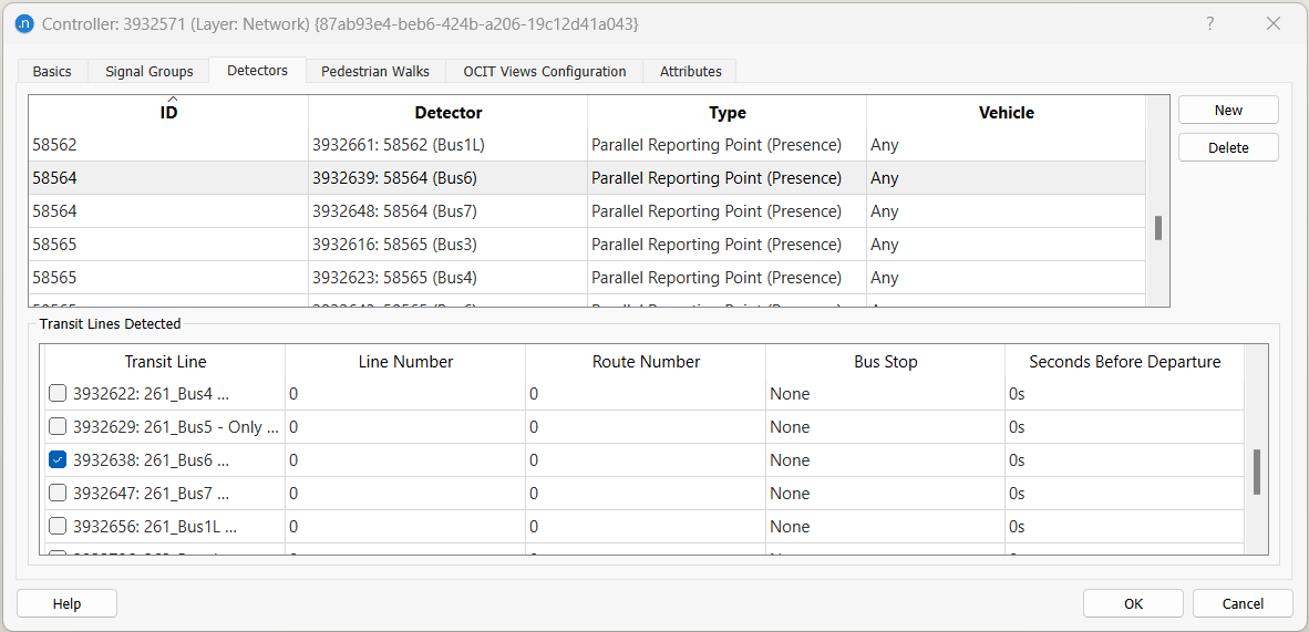
Detectors
The Detectors tab of the controller editor is used to match the detectors in LISA to the detectors linked to the controller in the Main tab.
If a detector is associated to one or multiple Transit Lines, it will act as a calling point and send OCIT R09 telegrams to the controlled whenever an equipped vehicle serving that line is detected by the detector. The content of the telegram generated by a line (line number and route number) is set in the OCIT tab of the Transit Line.
There are several types of LISA detectors:
-
Standard: This detector works like standard detectors; it sends presence while a vehicle of any type is on top.
-
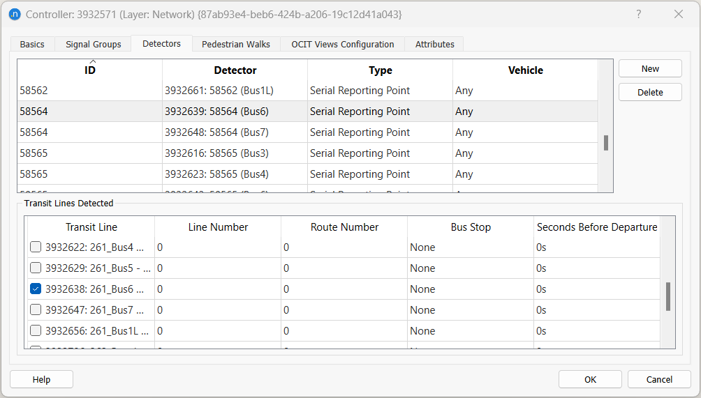
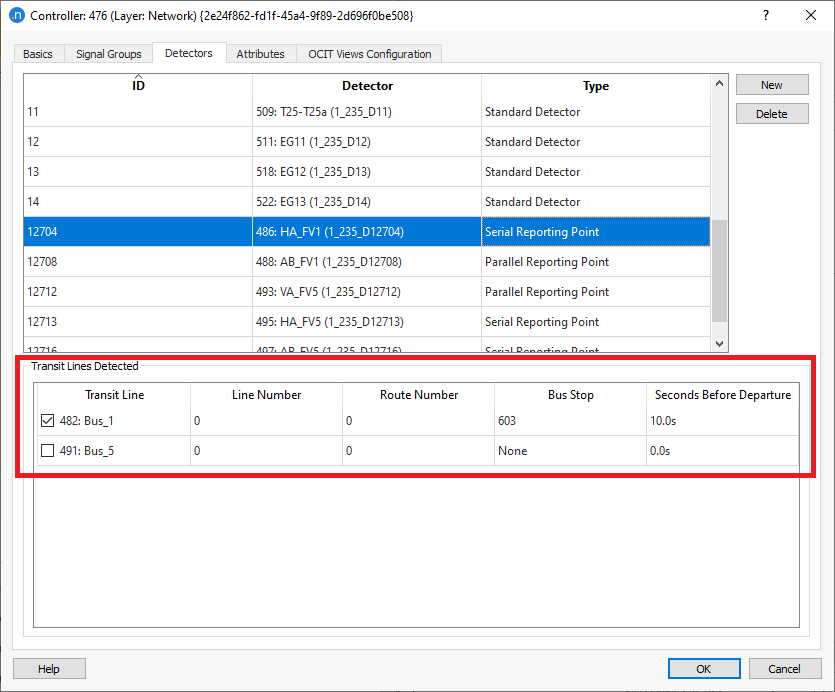
Serial Reporting Point: This detector sends a transit telegram when a transit vehicle of the transit lines selected in the "Transit Lines Detected" table is detected.
-
Parallel Reporting Point (presence): This detector sends a presence signal (like detectors) when an equipped vehicle is on top. The detector sends presence while a vehicle of any of the selected transit lines in the "Transit Lines Detected" table is on top of the detector. If no transit line is selected, it should send presence while an equipped vehicle of any type is on top of the detector.
-
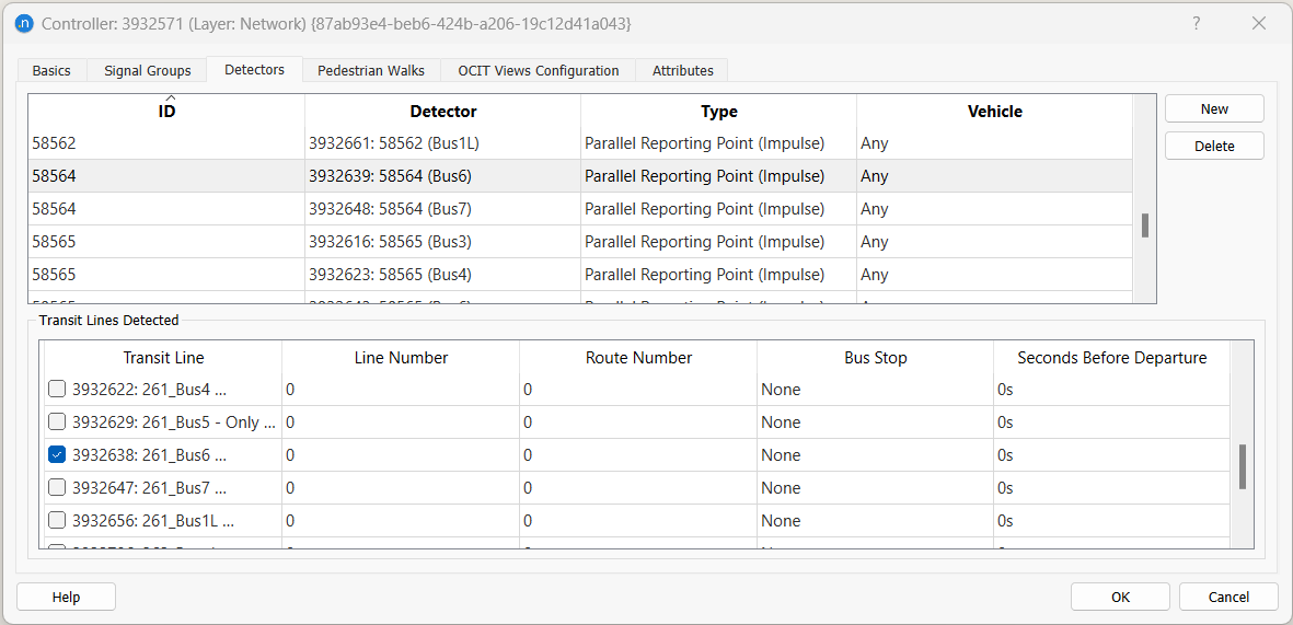
Parallel Reporting Point (impulse): This detector sends a one second presence signal (like detectors) when an equipped vehicle gets on top. The detector sends presence as a vehicle of any of the selected transit lines in the "Transit Lines Detected" table gets on top of the detector. If no transit line is selected, it should send a one second presence signal every time an equipped vehicle of any type gets on top of the detector.
If Standard detector type is chosen, the window "Transit Lines Detected" is freezed as there is no option for transit vehicles to send messages via this detector type. If Parallel Reporting Point or Serial Reporting Point is chosen, the lower part "transit lines detected" is enabled and transit lines can be selected. In the case of a Serial Reporting Point, minimum one transit line must be selected. In the case of a Parallel Reporting Point, if none transit lines are selected, it should send presence while an equipped vehicle (if any) of any type is on top.
For example, in the case of an emergency vehicle, a detector should be defined as Parallel Reporting Point with no transit lines associated, and an emergency vehicle should be created as a vehicle type (% equipped).
- Line Number: The line number must be inserted in the transit line tab named OCIT.
- Route Number: The route number must be inserted in the transit line tab named OCIT.
- Bus Stop: If selected, then the message will be sent when the vehicle departs from this transit stop.
- Seconds Before Departure: If the Bus Stop is selected, an option to send the message seconds before the bus departs from that transit stop.
For Serial and Parallel Reporting Point detector types, the Detector measuring capabilities "Occupancy" and Equipped Vehicle" must be checked.
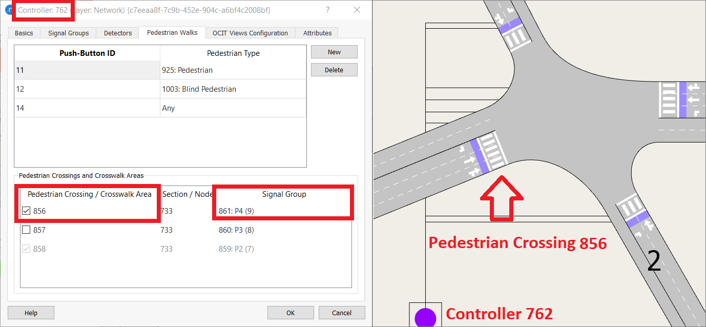
Pedestrian Walks
To allow the Push-Buttons functionality for pedestrians, the Pedestrian Crossings or Crosswalk Areas at the controlled junction should be assigned to a signal group in the Nodes Editor.
These Pedestrian Crossings and Crosswalk Areas will then appear in the Controller Editor > Pedestrian Walks tab > Pedestrian Crossings and Crosswalk Areas and the user can assign each or multiple Pedestrian Crossings and Crosswalk Areas to a Push-Button ID in the LISA Controller configuration.
It is also available the option to assign the Push-Button ID to a specific Pedestrian Type. This setting tells whether presence should be sent only when a pedestrian of a specific type is waiting, or any pedestrian of any type.
The screenshots below show how a Pedestrian Crossing/Crosswalk Area with a signal group and two different Push-Button IDs, one for pedestrians with visual impairment (Blind) and one for pedestrian with no visual impairment, would be configured.
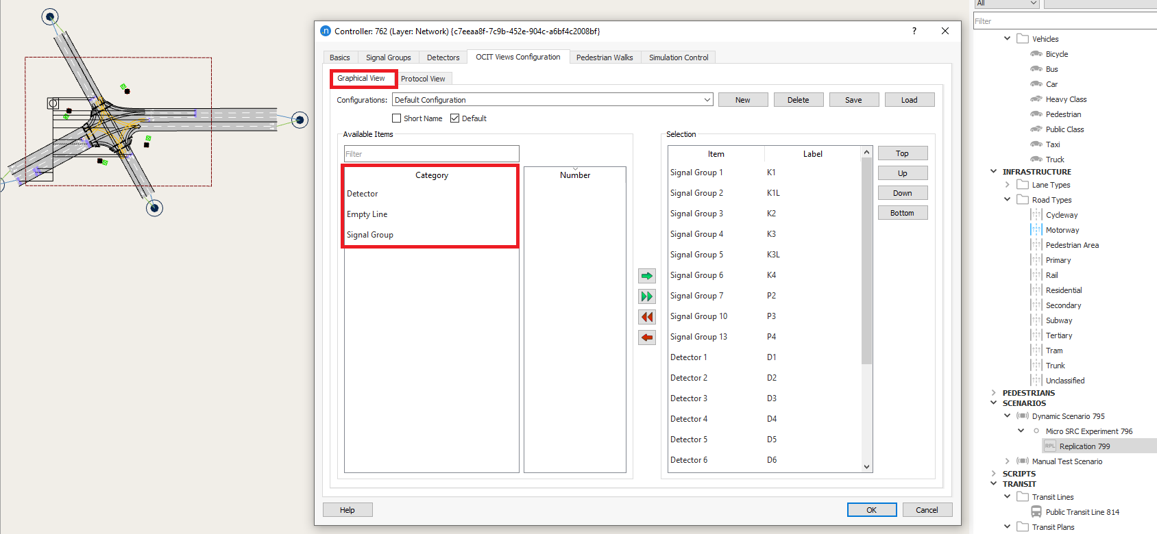
OCIT Views Configuration
The OCIT Views Configuration tab is used to configure the content of the graphical view and of the protocol view shown in the controller during the simulation.
Note that the available items in the protocol view configuration only reflects a minimum set of default items until you run the first simulation: when the LISA controller emulator is run for the first time, it tells to Aimsun Next what user-defined variables (AP Values) are defined in its logic, and those will be added to the list of available items. If the model is saved afterwards, those items are stored in the .ang file.
For example:
When we open the network file and access the Controller object > OCIT Views Configuration > Graphical View tab for first time, only the default attributes under the Category window appear until we launch the simulation. You can also check the attributes under the Protocal View tab.
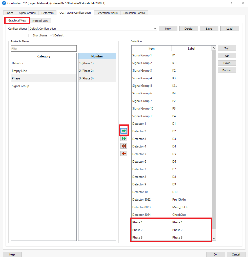
When we run the simulation for the first time, the attributes have been read and they appear under the Category window i.e.: Phases.
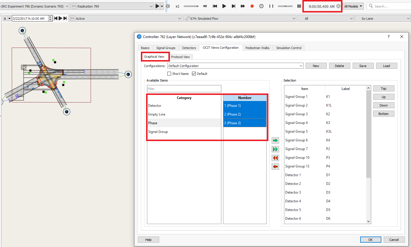
These attributes can be then selected to be visualized in the Simulation Control tab.
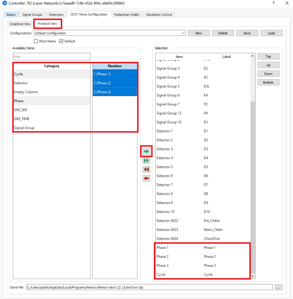
and selecting the attributes to appear in the Protocol View:
Accessing the Simulation Control tab, these attributes will appear in Graphical View.
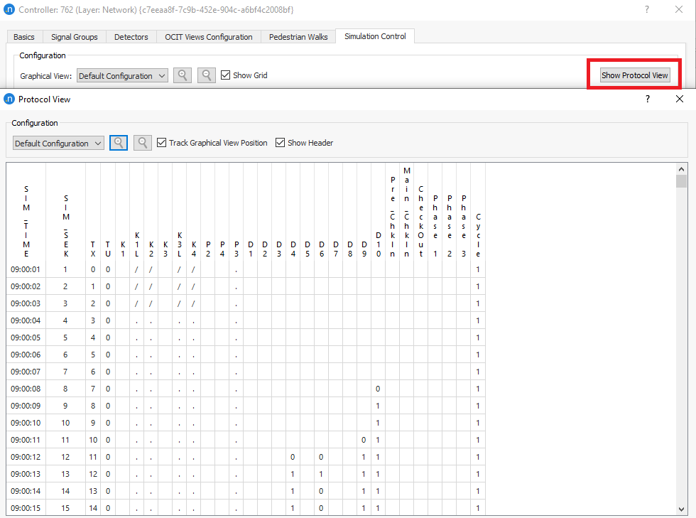
Clicking on the Protocol View we see the new attributes selected as well.
The attributes to appear in the Protocol View tab can be configured in the same way. The amount of the attributes that appear the Category window depends on the information exchanged between Aimsun Next and Lisa (files exported).
Running a Simulation with a LISA Controller
The simulation can be run from the replication as normal and the log window will show any relevant messages to confirm the operation of the LISA link.
When the simulation is run, the java VM is started and the signals are placed under LISA Control. If the communication fails, for example because the controller is not correctly configured, the signals will be frozen.
The signal program that is requested is the external ID of the Control Plan loaded according to the Master Control Plan. The OCIT flags (Central Mode, Individual Traffic and Transit Prioritization) that should be applied to the Control Plan are set in the Master Control Plan. Note that with LISA Central Mode activates and deactivates coordination, and turning on and off partial intersections is not supported.
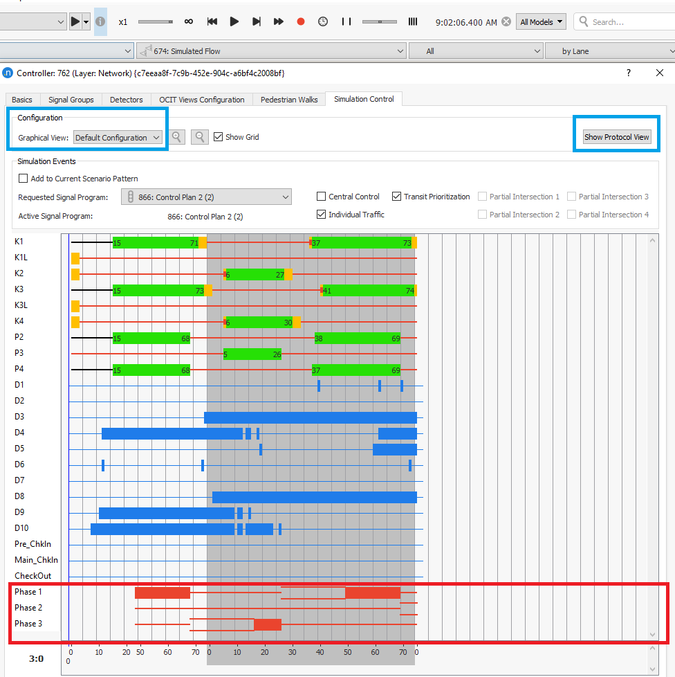
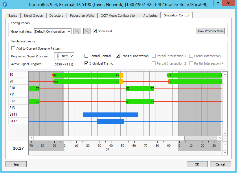
During and after the simulation, the Simulation Control tab of the controller editor can be accessed to see the graphical and protocol view. The Requested Signal Program drop-down and the checkboxes to its right can be used to change interactively the OCIT flags.
Manual actuations can be triggered by creating an OCIT Detection Pattern Template. Associating an OCIT Detection Pattern to the Scenario allows storing the detector actuations and any changes to the requested signal program and to the OCIT flags that are performed via the Simulation Control window.
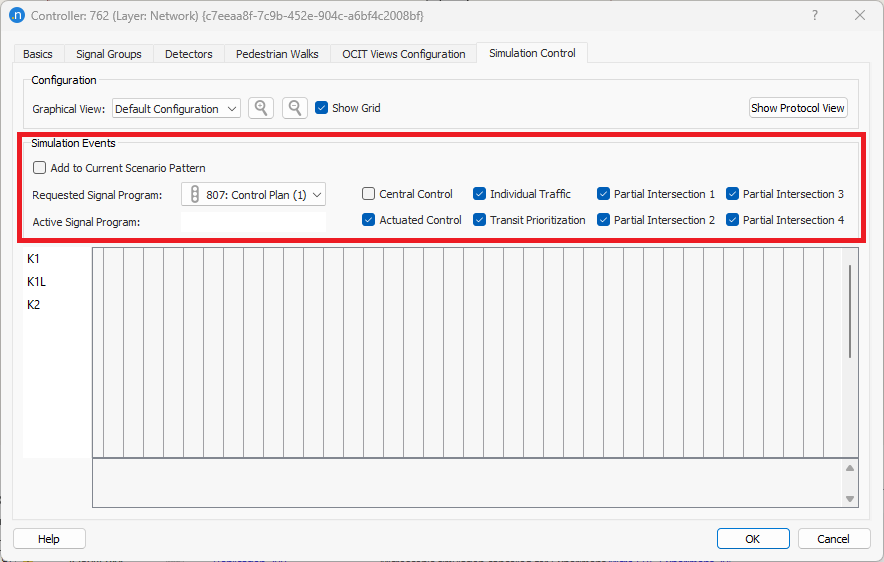
To perform testing the user can apply modifications with the option "Simulation Events" manually (on the fly) during the simulation as many times as the user wants via the controller object. Simulation events enable the user to modify the control plan and other flags during the simulation (visible only during simulations and playbacks). The simulation events in question are the following:
- switch to another signal program
- turn on/off central control
- turn on/off traffic actuations
- turn on/off actuated control
- turn on/off transit prioritization
- turn on/off partial intersections
Once the simulation is launched, open the Controller object > Simulation Control Tab. Modify the Requested Signal Program to set a control plan and activate/deactivate the corresponding OCIT flags manually (only during the simulation). The user has also the option to save those changes in an OCIT Detection Pattern by selecting the Add to Current Scenario Pattern option to reproduce exact the same simulation with the modifications performed manually and stored.
For more options on how to use simulation events, see OCIT Detection Patterns.