Valid Target Lanes
Valid Target Lanes 
The calculation of the Valid Target Lanes is common for all dynamic models (Meso, Micro, and Hybrid). The set of valid target lanes are the input for the lane selection and lane changing models.
The calculation of the Target Valid Lanes is based on the traffic conditions in the section, the turn lanes specified for next junction, and the possible obstacles on the path to the junction including incidents, compulsory reserved lanes, closed lanes, turn closures, and the presence of a transit stop, in case of a transit vehicle. The influence of each element is determined by the following parameters:
- Turning movement: For each turn, the turn look-ahead distances or anticipation is defined. This is the distance upstream where vehicles become aware of the feasible lanes for their planned turning movement. The next figure shows an example of the turning movement from Section C to Section D with three different turn look-ahead distances (X, Y, and Z). The lanes used in the turn are the two rightmost in sections A and B and the three rightmost, including the side lane, in section C. The influence of each distance depends on the type of model used:
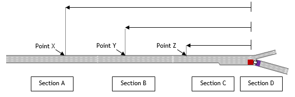
Note that point X is inside section A, point Y inside section B and point Z inside the last section before the turn, section C. Note that, in a mesoscopic model, any influence point inside a section is taken into account at the start of the section.
-
Mesoscopic model:
-
Point X: A vehicle with look-ahead distance reaching point X upstream that enters section A and subsequently sections B and C is influenced by turning movement C-D, so the valid target lanes are the two rightmost lanes.
- Point Y: A vehicle with look-ahead distance reaching point Y upstream that enters section B and subsequently section C is influenced by turning movement C-D, so the valid target lanes are the two rightmost lanes.
-
Point Z: A vehicle with look-ahead distance reaching point Z upstream that enters section C is influenced by turning movement C-D, so the valid target lanes are the three rightmost lanes.
-
Microscopic model:
- Point X: A vehicle with look-ahead distance reaching point X upstream is not influenced by turning movement C-D before point X, so the valid target lanes are all section lanes. After point X, the vehicle in sections A B and C is influenced by turning movement C-D, so the valid target lanes are the two rightmost lanes.
- Point Y: A vehicle with look-ahead distance reaching point Y upstream is not influenced by turning movement C-D before point Y, so the valid target lanes are all section lanes. After point Y, the vehicle in sections B and C is influenced by turning movement C-D, so the valid target lanes are the two rightmost lanes.
-
Point Z: A vehicle with look-ahead distance reaching point Z upstream is not influenced by turning movement C-D before point Z, so the valid target lanes are all section lanes. After point Z, the vehicle in section C is influenced by turning movement C-D, so the valid target lanes are the three rightmost lanes.
-
Incident presence: Each incident created by a traffic management action has a visibility distance that defines the distance upstream where the vehicles are aware about the presence of the incident.
-
Reserved Lanes: All reserved lanes of a section have a visibility distance that defines the distance upstream where the vehicles are aware about the presence of the reserved lanes.
-
Closed Lanes: Each lane closure created by a traffic management action has a visibility distance that defines the distance upstream where the vehicles are aware about this lane closure.
-
Turn Closure: Each lane closure created by a traffic management action has a visibility distance that defines the distance upstream where the vehicles are aware about this turn closure.
-
Transit Stop: Each Transit Stop has a visibility distance that defines the distance upstream where the transit vehicles that dwell at this stop are aware about it.
The calculation of the Target Valid Lanes for a vehicle is not restricted to a specific number of turning movements and considers the effect of all obstacles and turning movements in all sections determined in its path plan if the distance from the vehicle to obstacle/turning movement is less than the visibility or look-ahead distance of each element.
The calculation of the Valid Target lanes generates different results depending on the type of model for each vehicle :
-
Mesoscopic model: The mesoscopic model generates one set of valid lanes considering the "Visibility distance" of all obstacles and the look-ahead distance defined at level of turn.
-
Microscopic model: The Microscopic model generates two sets of valid lanes considering the "Visibility distance" of all obstacles and the Look-Ahead and Critical Look-Ahead defined at level of turn. This calculation returns:
-
Set of Target Lanes determined by Zone 3 influence (TL3)
- Set of Target Lanes determined by Zone 2 influence (TL2)
Hybrid Model: The hybrid model generates one set of valid lanes in the meso areas and two sets of valid lanes in the micro areas. The propagation of the look-ahead distance of the mesoscopic areas onto the micro areas affects the set of target lanes determined by Zone 3 influence, as the mesoscopic look-ahead distance is considered as a Critical Look-Ahead.
The propagation of the look-ahead distances of the micro parts onto the mesoscopic parts uses the Critical Look-Ahead as look ahead distance.
Lane Selection model for Roundabouts 
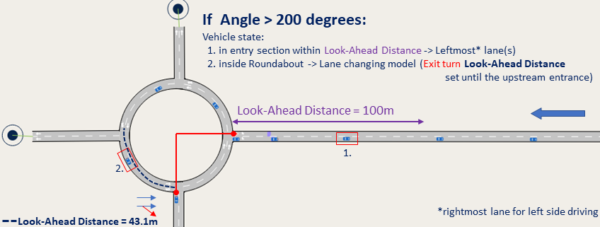
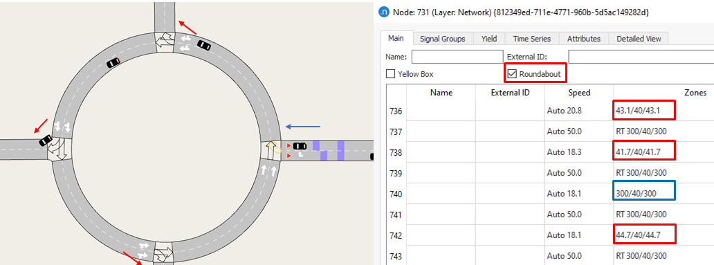
The lane selection model for roundabouts is active by default when creating a roundabout with the roundabout editing tool. At the Main tab of any node, find a checkbox named "Roundabout" to toggle on if you want this model to be applied. It applies to both micro and meso models.
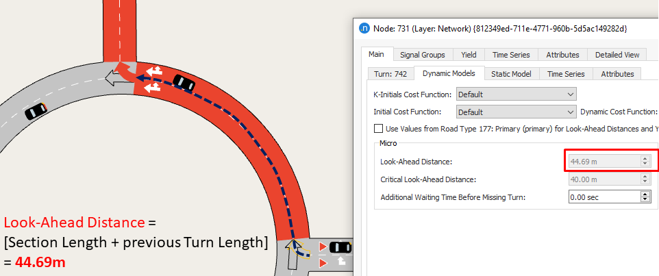
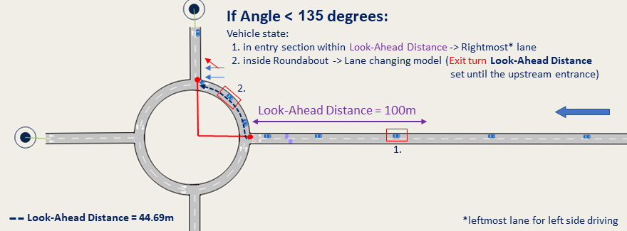
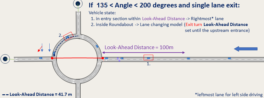
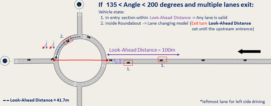
When active, the model modifies the valid lanes on the entry sections upstream of a roundabout, using the Look-Ahead Distance specified in the entrance turn of the roundabout as the point where the lane selection model for roundabout is activated. If the Look-Ahead Distance is bigger than the section length, then the distance is propagated upstream, so that vehicles queue in lanes according to the destination exit. The lane selection criteria is based on the angle formed by the turn entry and turn exit points of the roundabout.
In addition, when the Roundabout checkbox is activated, the Look-Ahead Distance of the exit turn from the roundabout is adjusted to the section length plus the length of the previous turn so that the lane selection can be made also in the turn.
Find below how the model handles each scenario:
-
If the angle formed by the entry and exit points is less than 135 degrees, the vehicles will be positioned on the rightmost lane on the entry section (leftmost lane for left side driving).
-
If the angle is between 135 and 200 degrees (straight exits), the vehicles use the same lane as for right turns in two lanes roundabout approaches unless the exit turn allows both roundabout lanes to exit the roundabout. In this latter case as in the case of roundabouts of more than two lanes, the two rightmost lanes of the entrance section can be used.
-
For left exits (located at more than 200 degrees), the vehicles use the leftmost lanes (rightmost lane for left side driving).