Using Advanced Signal Controls
Note about licenses: These exercises require a license for Aimsun Next Pro Meso, Pro Micro, Advanced, or Expert Editions.
Introduction
These exercises use signal controls in more complex situations, including transit priority and actuated control.
The backup copies of the files related to this exercise are in [Aimsun_Next_Installation_Folder]/docs/tutorials/10_Advanced_Control.
Exercise 1. Giving Priority to a Vehicle Type
At a controlled intersection, we can give priority to a selected vehicle type. In this example, we will give priority to two tram lines: L-Tram1, and L-Tram2 which run the same route in opposite directions.
We will change the signals from a fixed time plan – where every cycle is the same – to a plan that calls a tram-specific phase only if it is needed. When this phase is called, it adjusts the times of preceding phases by ending them early, as long as they have already run for a minimum time.
The first task is to review the routes and ascertain where signal priority should be used. Select the routes in the Project > Transit folder to the right of the 2D view.
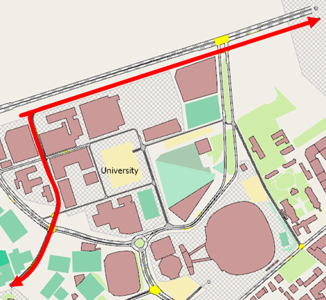
There are three nodes on the tramlines:
- Node 1 (object ID = 2071)
- Node 2 (object ID = 2030)
- Node 3 (object ID = 2040)
There are signals at Nodes 1 and 3 but node 2 simply has a Yield sign in operation.
1.1 Adding detectors
To provide traffic-light priority at the two signalized junctions, we must first position detectors to register that a tram is approaching the junction and, later, that the tram has left the junction.
To add the detectors:
-
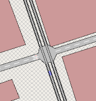
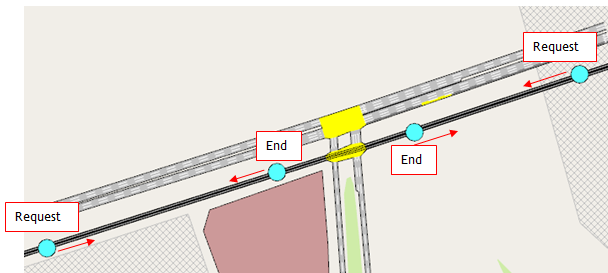
Add the two detectors that will activate the tram phase and place them at an appropriate distance around the node. The distances pictured below are acceptable.
-
Add two additional detectors at the exit of the intersection, just after the node, to mark the end of the tram phase. Refer to the illustrations of nodes below.
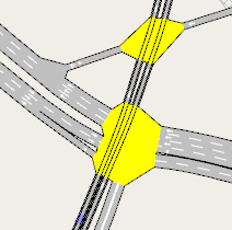
Node 1:
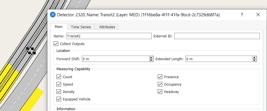
These detectors must be able to recognize equipped vehicles using this line. Therefore, the trams from line 1 and 2 must be suitably equipped and the detectors must have the Equipped Vehicle measuring capability enabled.
-
Double-click on each detector used and tick Equipped Vehicle.
-
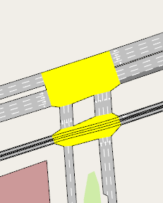
Repeat the placement of detectors for Node 3 as pictured below:
1.2 Specifying equipped vehicles
To specify the percentage of equipped vehicles:
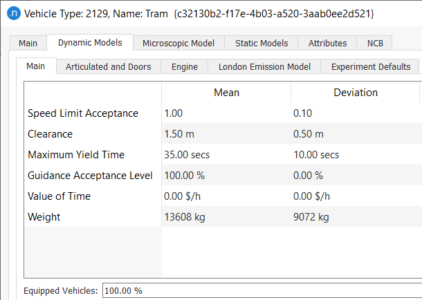
- Open the Vehicle Type: Tram dialog and set the percentage of trams that are Equipped Vehiclesto 100% as illustrated below.
1.3 Creating control plans
Now we need to create priority control plans for the signalized nodes 2071 and 2040.
For Node 2071
To create a priority control plan (Node 2071):
-
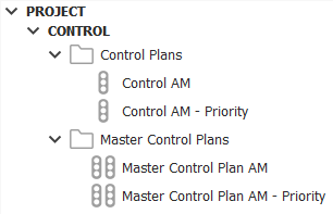
Duplicate the Control AM plan and rename it Control AM – Priority.
-
Repeat step 1 for Master Control Plan AM and replace the control plan, renaming it to Master Control Plan AM - Priority.
-
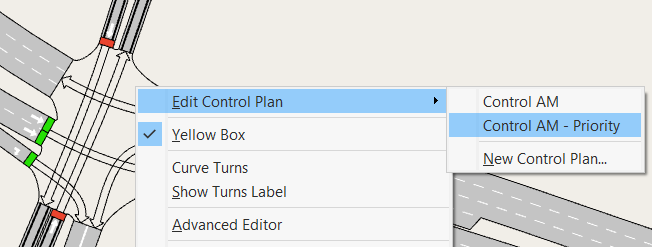
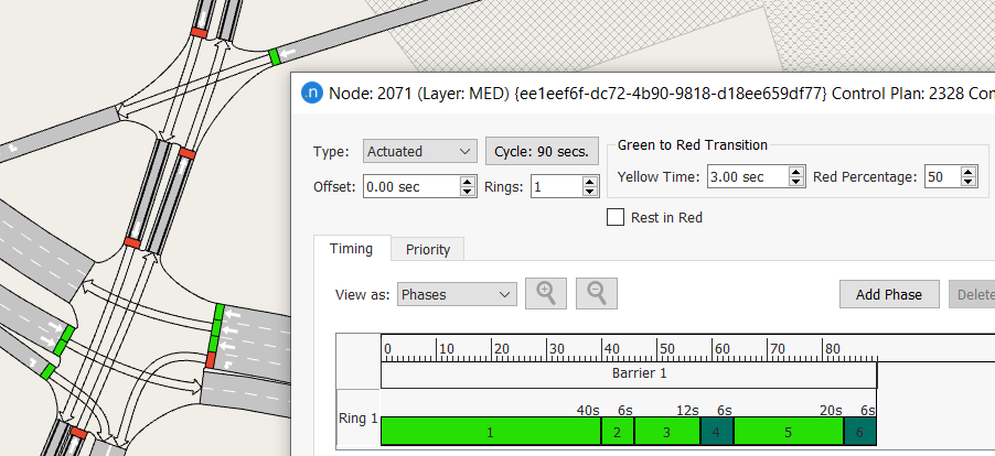
Open the priority control plan for Node 2071.
In the normal situation (not priority), phase 5 is the tram phase and is run in each cycle.
-
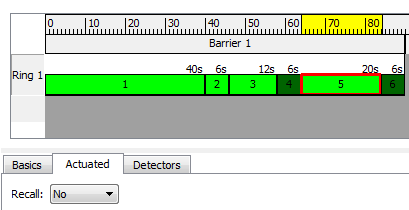
We want this phase to be activated only by a tram traveling past the detectors. To do so, we first need to change the Recall parameter from Recall: Max (which calls the phase for the maximum green time every cycle) to Recall: No (which only calls it when required and otherwise skips it).
-
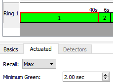
In the other actuated phases (phases 1, 2, and 3), we will lower the Minimum Green value so that the phase ends before reaching the maximum green value in the event of a priority call. When the tram gets to the intersection, because it has priority, it will end the current phase (for other vehicles) if the minimum green time has elapsed. Set a value of 2 seconds for phases 1, 2, and 3.
-
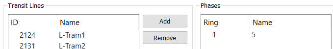
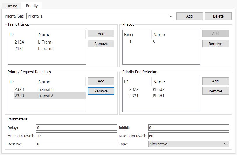
Now we will specify the preemption characteristics. Click Add to add a priority set of transit lines form the Select Objects of Type ... dialog. For this set, tick lines L-Tram1 and L-Tram2; the phase that gives right of way to the tram lines is phase number 5.
-
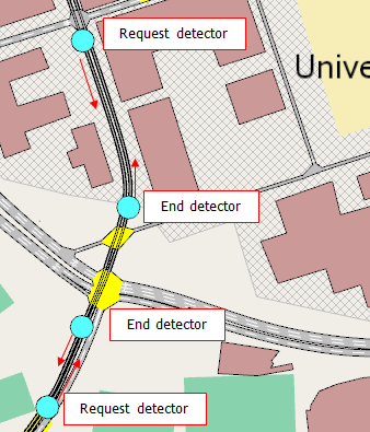
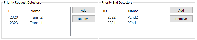
In the Priority Request Detectors group box, click Add and, in the 2D view, click on the two detectors that provide the request for priority. In the Priority End Detectors group box, repeat for the two detectors ending the request (all four detectors are shown listed below).
-
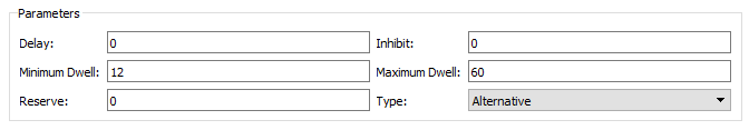
In the Parameters group box, set Minimum Dwell time to 12 seconds and Maximum Dwell to 60.
-
In the Type drop-down list, there are two types of priority: Alternative and Serve All. Select Alternative, which will cause the dwell phase to change to green as soon as the minimum green times of the current green phases are past and the interphase finishes, ignoring intermediate phases.
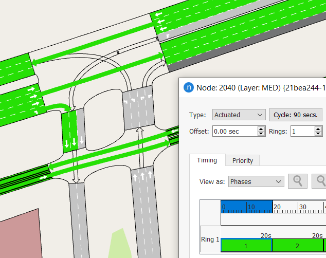
For Node 2040
To create a priority control plan (Node 2040):
-
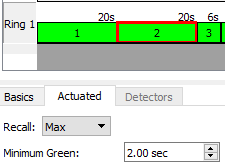
Open the control plan for Node 2040. The tram phase is number 1 but this time we will not mark it as Recall: No because it is shared with other movements and we don’t want to cause these movements to be held up until a tram passes.
-
For all other actuated phases (2, 3, 4, 5, and 6), lower the Minimum Green value to 2 seconds. This means that the phase can end before reaching the maximum green value in the event of a priority call. The tram can then end the phases early, but only if their minimum green time has elapsed.
-
Edit the priority tab as pictured below.
1.4 Running the new simulation
To run the new simulation:
-
Duplicate the current scenario and experiment and append their names with Priority rather than Base.
-
Open the duplicated scenario and select the Master Control Plan Master Control Plan AM - Priority.
-
Run the simulation to observe how the priority calls work.
-
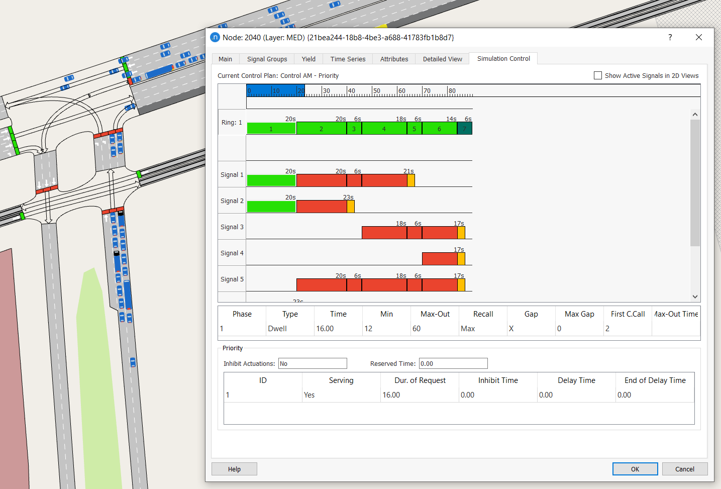
Open the Simulation Control folder in the Node dialog(s) during the simulation to see the active signals and phases in action.
-
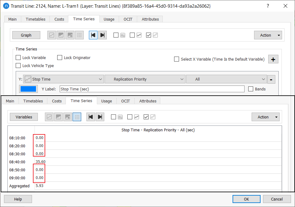
Open the Transit Line dialog(s) for the tram lines. The stop-time statistics should now = 0.00 because they have priority and do not stop at the traffic lights. The screenshot below overlays the table view below the choice of variable (Stop Time).
Exercise 2. Defining Actuated Control
In this exercise, we will edit traffic control to define an actuated control with a dual-ring structure instead of fixed timings. Straight-turn movements are considered to be ‘as one’ with their corresponding right-turn movement, because when the straight movement is allowed the right turn will not interfere with other turns.
For through and left movements, in order to implement a full dual-ring actuated control, we need to individually detect each call for a turn movement on the junction. To do this we will place an individual detector and traffic light into the model for each turn movement. Note: Lanes should not be shared by two or more turns.
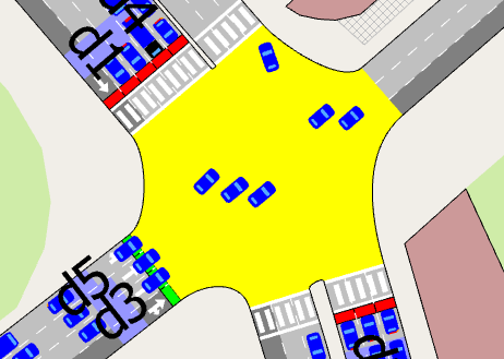
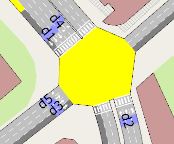
In the node pictured below (object ID 2062), the signal groups defined for the fixed control already fulfil these conditions.
2.1 Adding detectors
To add the required detectors:
-
Add the detectors required to detect calls for the various movements. This requires five detectors (covering 1 or 2 lanes each, depending on the movement):
-
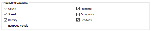
As a minimum requirement, detectors must be capable of detecting vehicle presence (although some other examples of actuated control require count capability). Check that all your new detectors have the Measuring Capability Presence ticked:
2.2 Setting the actuated control, ring, and barriers
To set the actuated control, ring, and barriers:
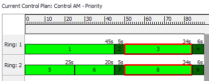
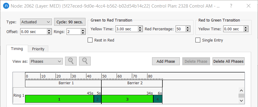
- Open the node's control plan Control AM - Priority and change its Type to Actuated.
- Set the number of rings to 2.
- Set View as to Phases to enable editing.
- Create a second barrier by dragging the line defining the right edge of Barrier 1 to the left.
-
Set Yellow Time as 3 seconds and untick Single Entry so that, when a barrier is crossed, a phase in every ring must receive green. As a result of these steps, the Control Plan dialog should resemble the screenshot below.
-
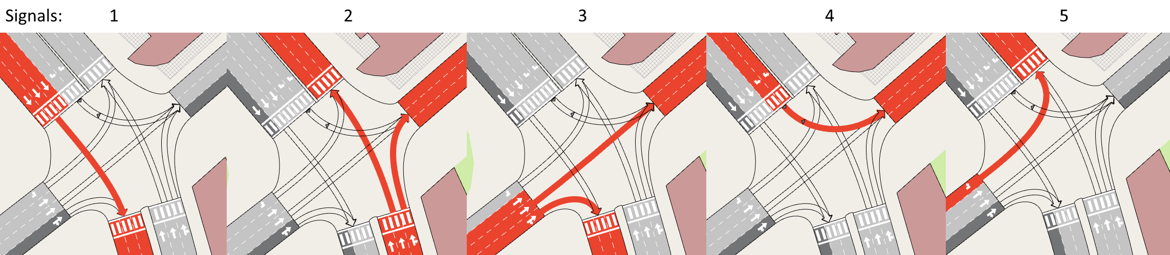
Define the phases: the first barrier will contain the movements from the north and south (1, 2, and 4), and the second barrier will contain the movements coming from the west (3 and 5).
In the first barrier, the movement down (1) is compatible with the movement down-left (4) and the movement up (2), so these last two will be together in one ring, and the first in the other.
The image below pictures how this control could be defined:
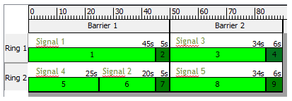
Signals for each phase are defined in the Basics tab.
- Phase 1: Signal 1
- Phase 5: Signal 4
- Phase 6: Signal 2
- Phase 3: Signal 3
- Phase 8: Signal 5
The next steps involve filling in the parameters on the Actuated tab.
-
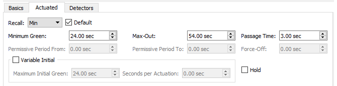
For Phase 1, set the Recall to Min so that it gets a green for each cycle, and tick the adjacent Default option.
-
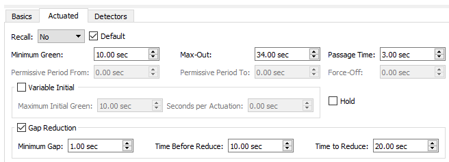
For Phase 3 and Phase 8, tick both as Default.
-
Tick Gap Reduction and set Minimum Gap as 1 second, Time Before Reduce as 10 seconds, and Time to Reduce as 20 seconds.
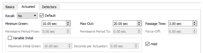
Phase 5 is not a default phase and needs no special conditions.
<br/>
-
For Phase 6, tick Default Hold so that it stays green, even in the absence of calls, until the barrier time is reached.
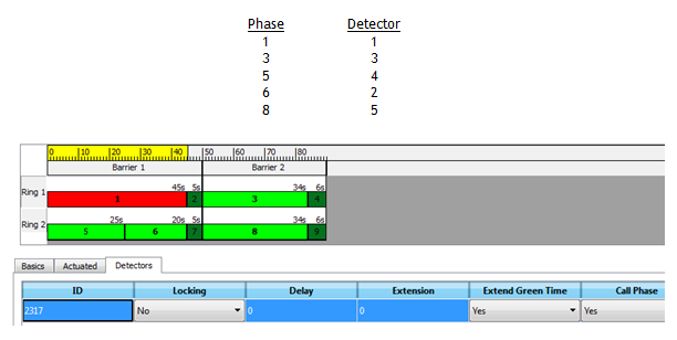
The next step defines the detectors that will provide the call for a green phase when they detect the presence of vehicles.
-
Click the Detectors subtab and choose detectors by selecting each signal, clicking Add selecting the detector in the 2D view.
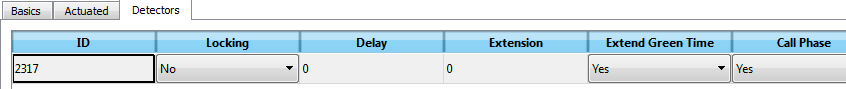
The necessary associations are pictured below.
-
Run a simulation to observe how actuated control works.
-
Open the Simulation Control folder in the Node dialog during the simulation to see signals and phases in action.