Working with 3D
Note about licenses: These exercises require a license for Aimsun Next Pro Micro, Advanced, or Expert Editions.
- Exercise 1. Opening a 3D View
- Exercise 2. Adding Cameras
- Exercise 3. Creating 3D Buildings
- Exercise 4. Creating 3D Images
- Exercise 5. Viewing 3D Vehicle Properties
- Exercise 6. Adding a 3D Shape (Stadium)
- Exercise 7. Adjusting the Altitude of Sections
- Exercise 8. Viewing a 3D Animation
- Exercise 9. Tracking a Vehicle with a Camera
- Exercise 10. Creating a Camera Route
Introduction.
In these exercises, you will learn how to move around a 3D view, add cameras, create buildings, add textures, work with other 3D shapes, adjust the altitude of sections, track vehicles, and create a camera route through a 3D model. We will start from a 2D network, visualize it in 3D, and enhance its appearance to give it a more realistic character.
The files related to these exercise are in [Aimsun_Next_Installation_Folder]/docs/tutorials/4_3D_Editing.
Exercise 1. Opening a 3D View.
The most common Aimsun Next view is the 2D view where most modeling tasks take place. You can also open a 3D view, which displays to the right of the 2D view.
To open a 3D view:
-
Open the Aimsun Next file Initial_3D_Editing.ang.
-
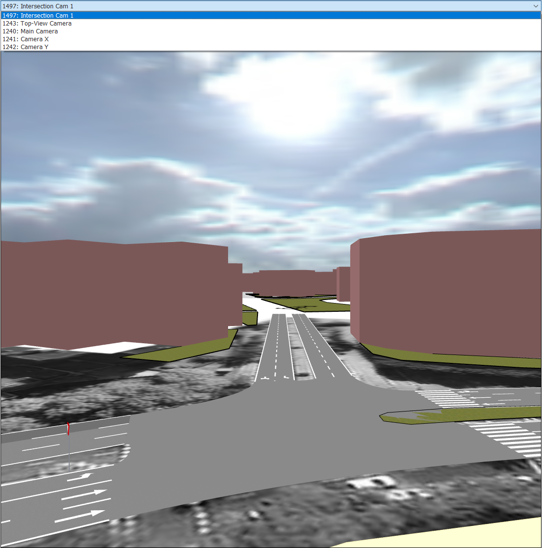
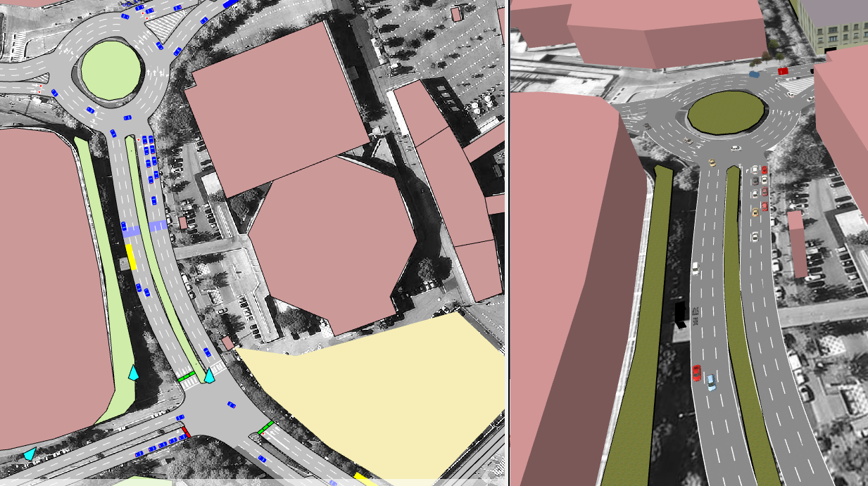
Select View > New 3D View to open a new 3D View window. The 2D view and the 3D view appear side by side, as seen in the screenshot below. You might need to drag the left-hand border of the 3D view to enlarge the view and see the relevant details.
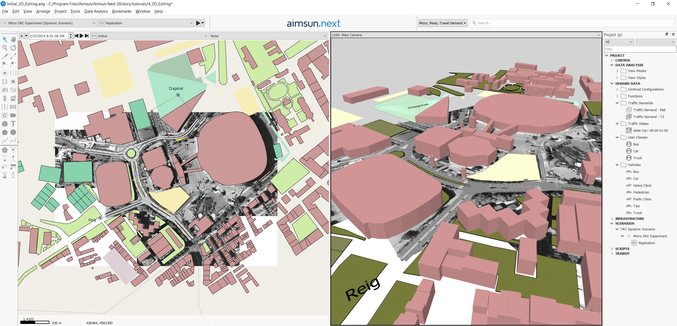
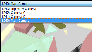
Four default cameras are included with every 3D view (Main Camera, Top-View, Camera X, and Camera Y).
-
To change cameras views, select cameras from the drop-down list in the top left-hand corner of the 3D view. You can also pan and zoom around the 3D view as with the 2D view.
Exercise 2. Adding Cameras
Before continuing, close the 3D view you opened in the previous exercise by right-clicking the mouse on the 3D view and selecting Close. We are now going to add a new camera to the network. Cameras are always added in the 2D view, using the Create a Camera tool  .
.
We will place the new camera so that it points toward the main intersection.
To create a new camera:
-
Arrange the 2D view so that you can see the main intersection in the screenshot below.
-
Click
and then click in the 2D view to the right of the intersection to place the new camera. The tapered end of the camera shape represents its 'lens'. -
Click the Rotate tool
 and then click on the camera (you will see the axes that the camera is based upon). Rotate the camera so that it points toward the main intersection. When you are happy with the angle, click Esc to deselect the Rotate tool.
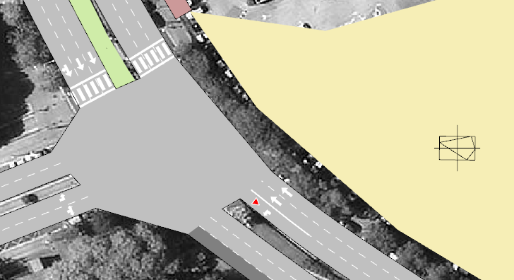
-
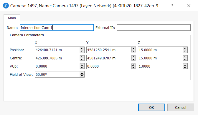
Double-click on the camera to open its dialog and enter a Name so that you can identify it later in the 3D view's list of cameras.
-
Open a new 3D view like you did in Exercise 1.
-
From the list of available cameras in the 3D view, select your new camera. If you don’t see the whole intersection, you can correct the position of the camera by moving and rotating it so that it faces the main junction as shown in the next screenshot.
-
To refine the view even more, click on the camera in the 2D view and then:
- Use the keyboard arrows to move the camera forward, backwards, left, and right
- Hold down Shift and use the up and down arrows to move the camera up and down
- Hold down Ctrl and use the arrow keys to rotate the camera.
Aim for a camera view similar to the one illustrated above.
Exercise 3. Creating 3D Buildings
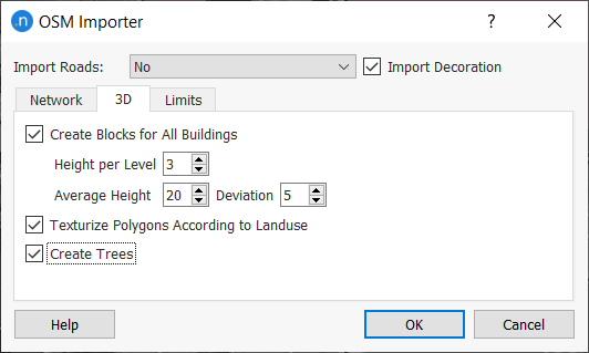
The simple network we are using was created by importing an OpenStreetMap file (see Exercise 1 in the Building a Model tutorial for a recap). When importing, we chose to Create Blocks for All Buildings on the 3D tab, using a Height per Level of 3, an Average Height of 20m and a Deviation of 5m.
In these exercises, we will create a new building, give it a specific height, and add textures (i.e surfaces that look like recognizable walls and windows) which vary according to floor level.
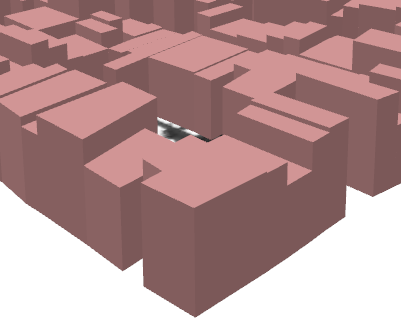
The screenshot below shows the effect of changing the polygons on the OpenStreetMap > Building layer into extruded polygons that have an average height but no further details to represent the buildings.
We will create similar polygons manually and add textures to them. But first we need to add and activate a 3D layer that will help us manage our objects.
3.1 Adding and activating a 3D layer
A 3D layer enables you to manage the visibility of your 3D objects and choose to make them editable or not as you work.
To add and activate a 3D layer:
-
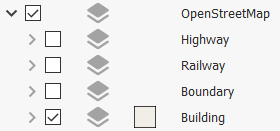
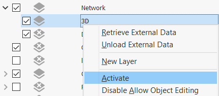
In the Layers window, right-click on Network and select New Layer.
-
Rename the new layer as 3D.
-
Right-click on 3D and select Activate.
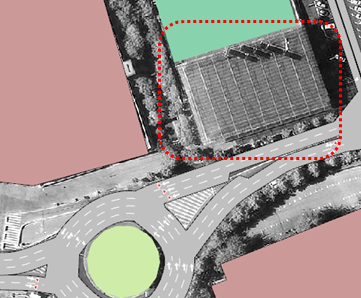
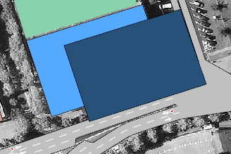
The screenshot below shows a 2D representation of a building in the network that has no polygon yet. It is just a background image. We will change this building into a 3D object in the next exercise.
3.2 Creating a new 3D building
This exercise needs to be done in the 2D view, so click in the 2D view to select it. Also, make sure that the 3D layer is active so that the new building is added to the correct layer.
To create a new 3D building:
-
Click the Polygon tool
 and, in the 2D view, draw a shape that covers the area of the building in the screenshot above (the grey rectangle, not the red-dotted outline).
 -
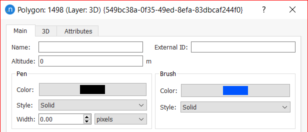
Double-click the new polygon to open its dialog.
-
In the Brush Drawing group box, change Color to blue and Style to Solid.
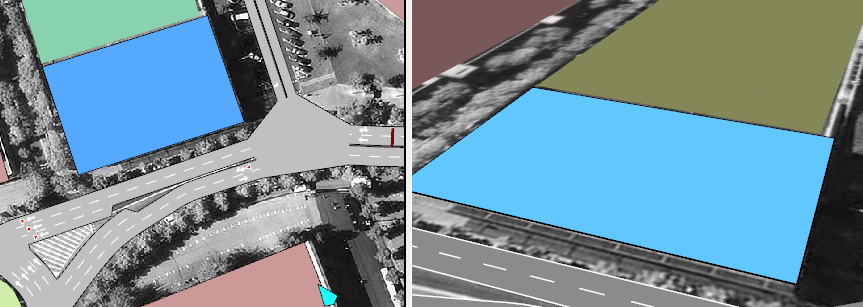
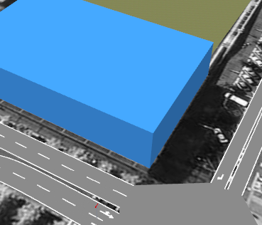
The screenshot below shows 2D and 3D views of the polygon. You might need to adjust the 3D view, using the mouse or keys, to get a similar perspective.
-
In the 2D view, right-click on the polygon and select Extrude. The polygon in the 3D view will change appearance to reflect the new 3D dimensions. This will form the ground floor of the new building.
-
In the 2D view, copy and paste the polygon. A new polygon will appear in both 2D and 3D views. Change the color of the copied polygon so that you can easily distinguish the two shapes. Keep the two polygons slightly separate for now, so you can easily select the one you need in later steps.
-
Right-click the first polygon to open its dialog and click the 3D tab.
-
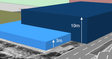
Set its Height as 3m.
-
Right-click the second polygon and set its Altitude as 3m and its Height as 10m. This will form the first floor of the building.
3.3 Adding textures to the new 3D building
In this exercise, we will add textures to the building to make it look more realistic.
To add textures to the new building:
-
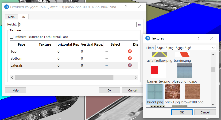
Select Window > Windows > 3D Info. This adds the 3D Info window to the Project folder to the right of the 3D view.
The Textures tab contains a list of graphics files representing elements like walls, windows, bricks, and many more.
-
In the 2D view, double-click the ground-floor polygon to open its dialog, and click the 3D tab.
-
Find the Laterals row and click in the Select cell.
-
Select brick1.png from the Textures dialog and click OK.
-
Click OK to close the ground-floor polygon dialog and double-click to open the first-floor polygon's dialog.
-
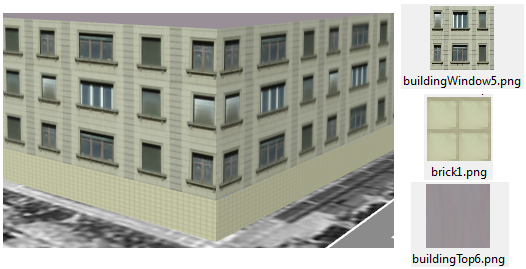
Add the following textures for these rows:
- Top: buildingTop6.png
- Laterals: buildingWindows5.png.
-
Drag the polygons so that the first floor sits on top of the ground floor to form a single building. In the 3D view, the building, with textures, should resemble the left-hand image in the screenshot below.
Tip: You can also drag textures from the 3D Info window directly onto the polygons in the 2D view (you might need to temporarily select and move one of the polygons to distinguish them when dragging textures).
When dragging textures, note the following options:
- Drag completely inside a polygon to apply the texture to the top face of the polygon
- Hold Ctrl and drag completely inside a polygon to apply the texture to the bottom face
- Drag onto a lateral line to apply it to all lateral faces
- Hold Ctrl and drag onto a lateral line to apply the texture only to that particular lateral face.
Exercise 4. Creating 3D Images
When importing an OpenStreetMap file, some 3D images, e.g. trees, are automatically created and placed in the layers named Natural and Landuse. In this exercise, we will create objects manually: first a tree and then a car-park entrance for our new building. The steps and methods are relevant to all available 3D objects.
To create 3D trees manually:
-
Click the Create a 3D Image tool
 .
. -
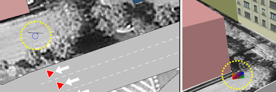
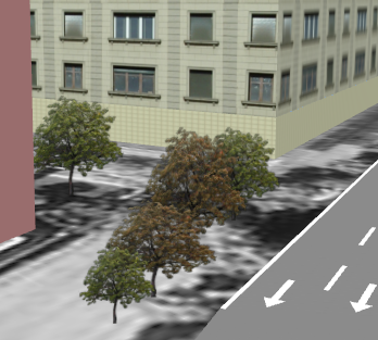
In the 2D view, click where you would like to create the 3D image (in our case, between the section and the building). You might need to zoom or pan the network view to find the right location.
The 3D object marker is displayed in the view, as circled below.
-
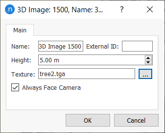
Double-click the 3D image marker to open its dialog.
-
Next to the Texture field, click the browse button and select the 3D graphic file tree2.tga.
-
Click OK to close the dialog.
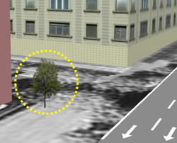
Notice that, in the 3D view, a tree has been placed at the corresponding location. Because the Always Face Camera option was automatically ticked, the image of the tree will always appear square-on to the view.
Copy and paste as many trees as you need. You can change the height and texture of these images by opening their dialogs in the 2D view and changing the settings. You can also select alterative types of tree, e.g. tree3.tga.
You can move, resize, or rotate trees by clicking on the objects in the 2D view and dragging the whole object, using the Rotate tool, or clicking and dragging their structural vertices (note that rotation is not effective when the Always Face Camera option is ticked).
Now we will add a car-park entrance to the ground floor of the building we created in Exercise 3.
To add a car park entrance:
-
Add a new 3D image parallel to the front face of the building.
-
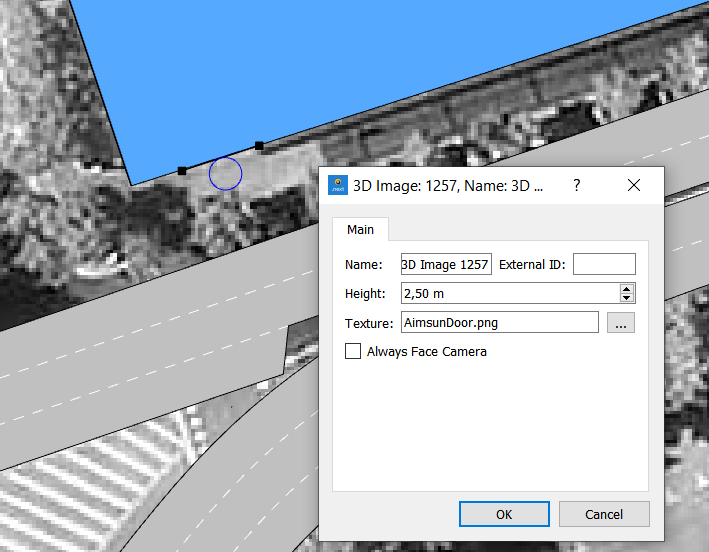
Double-click the image to open its dialog and change its Height to 2.5m
-
In Texture, select AimsunDoor.png texture.
-
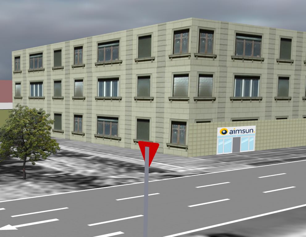
Untick Always Face Camera so that the object remains in the same orientation regardless of the viewing angle.
Your results should resemble the screenshot below.
Exercise 5. Viewing 3D Vehicle Properties
In this quick exercise, we will check the 3D properties of the different vehicles types used in the simulation: car, truck, and bus.
To check 3D vehicle properties:
-
In the Project window, open the Demand Data > Vehicles folder and double-click Car.
-
Click Microscopic Model tab > 3D Shapes subtab.
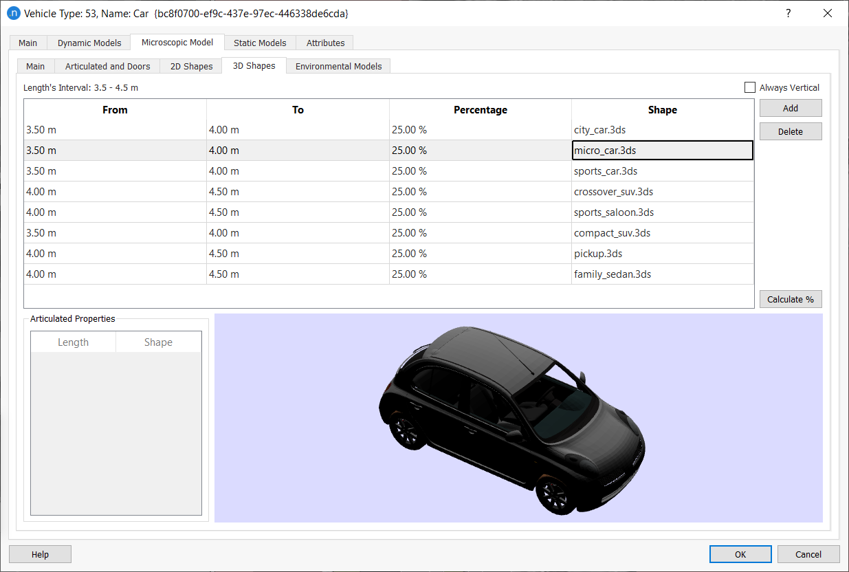
The dialog contains all the different types of car available in the model. It also lists their lengths (in intervals between 3.5m and 4.5m) and the percentage of lengths included (they must equal 100% for each From/To pairing – in the example there are two different intervals, with four entries for each, and each instance = 25%).
-
(Optional) Repeat for Bus and Truck vehicle types.
-
Click OK to close.
Note: If, for project reasons, you want to remove a particular vehicle design from the model, select its name and click Delete.
Exercise 6. Adding a 3D Shape (Stadium)
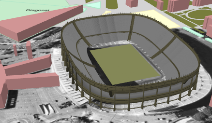
3D shapes are graphic files that represent objects you can include in a simulation to give location references. Typically, these are notable landmarks or recognizable buildings. You might need to use 3D shapes when adding textures to a basic building block is not sufficient to properly represent a building, landmark, or locale.
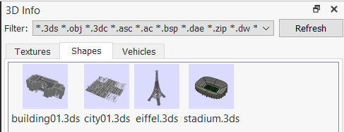
You can find the available 3D files on the Shapes tab of the 3D Info window (see Exercise 3).
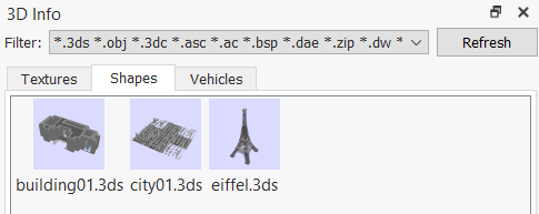
These shapes correspond to files in the Aimsun Next installation directory: Program Files/Aimsun/Aimsun Next version/shapes. In this exercise, we will use a 3D shape file named stadium.3ds, which you can find in the tutorial directory: [Aimsun_Next_Installation_Folder]/docs/tutorials.
Before we begin, copy this file into the .../shapes folder and click Refresh in the 3D Info window so that it appears in the list, as below (to the right).
To add the 3D shape (stadium):
-
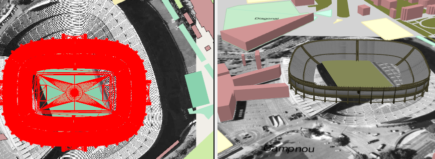
From the 3D Info window > Shapes tab, drag the stadium.3ds file into the 2D view and position it over the 2D representation of the stadium, as below.
-
Rotate the 3D shape using the Rotation tool
so that it sits over the 2D representation properly. Press Esc to deactivate the Rotate tool. -
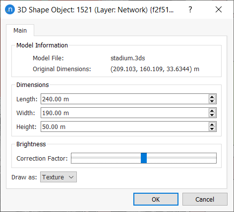
Double-click the 3D shape to open its dialog and enter the known Length, Width, and Height illustrated in the screenshot below.
-
Click OK to save your changes and close the dialog. The stadium 3D shape in the 3D view should now resemble the screenshot below.
Note that many different 3D shape file extensions are compatible with Aimsun Next: 3DS, OBJ, 3DC, ASC, AC, BSP, DAE, ZIP, DW, DXF, IV, OSG, LWO, OGR, FLT, and STL.
Exercise 7. Adjusting the Altitude of Sections
In this exercise we will adjust the altitude of sections to create slopes in the model. While making these adjustments in the 2D view, it is useful to check how they are visualized in the 3D view to ensure you are creating the right effect.
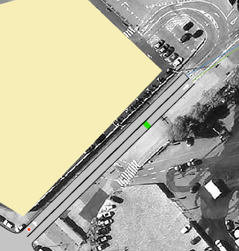
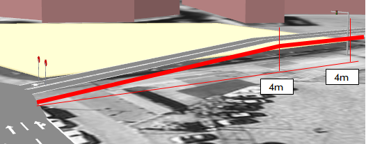
In our example, the Camp Nou car park has an altitude of 4 meters. The slope of the approach ramp section should climb from 0m to 4m, and the ramp descending from the car park should slope from 4m to 0m.
The screenshot below shows the ramps that lead up to and down from the car park in the 2D view.
To adjust the altitudes of the ramp sections:
-
Double-click on the 'up' section to open its dialog.
-
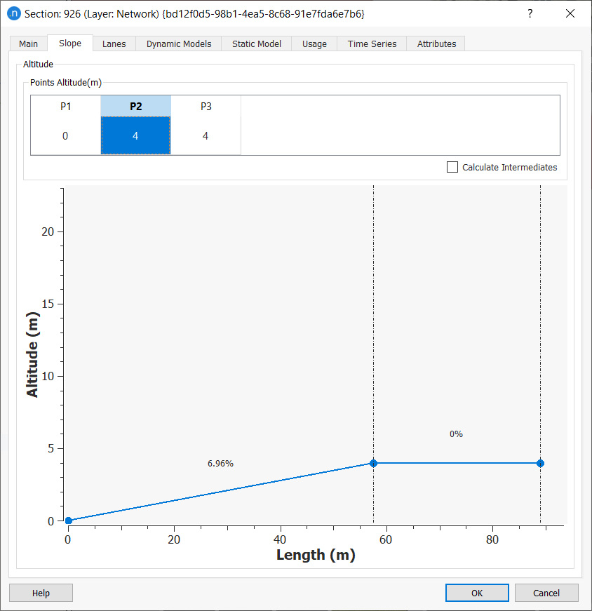
Click the Slope tab.
-
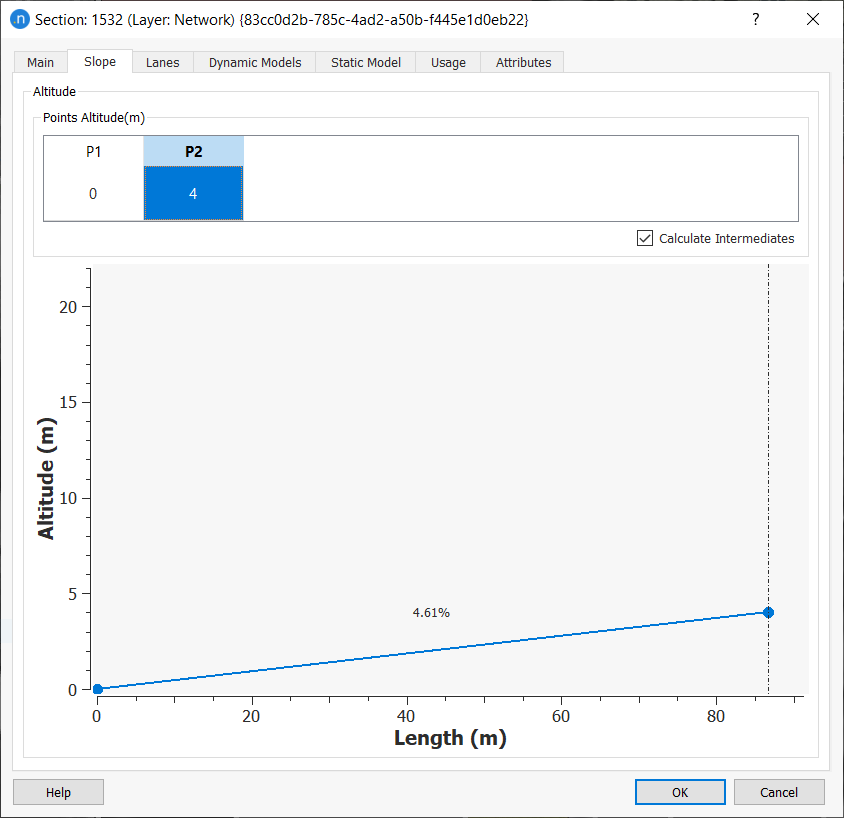
In the Altitude group box, click in the P2 cell and enter a value of 4 (meters). All intermediate points will be calculated automatically.
-
Click OK to close the dialog.
-
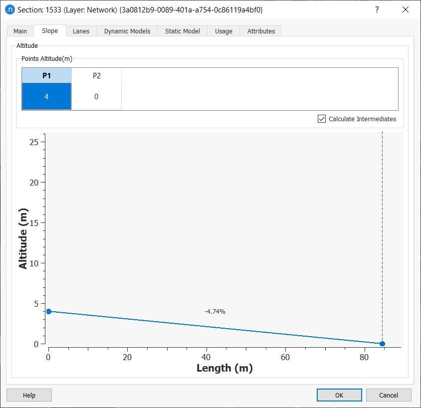
Repeat steps 1–4 for the 'down' section, but reverse the slope so that it descends from 4m to 0m.
There might be occasions when you want to flatten out a slope at some point, perhaps halfway along. Continuing with our example, to achieve this you can add a vertex to the section and give it a height of 4m.
To flatten out a slope:
-
In the 2D view, select the section or sections you want to adjust.
-
Click the Create a Vertex (Straight) tool
 .
. -
Draw a line across the section(s) where you want to place the vertex. The screenshot below shows two central vertices, one in each section.
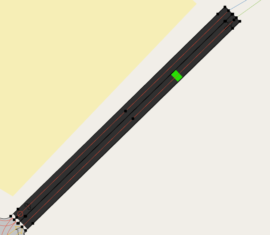
-
To add height to a vertex, hold down Ctrl and left-click on the vertex. Now move the cursor upwards to increase the height of the vertex (to 4m). Conversely, you can move the cursor downwards to lower the height. The change of height is displayed next to the vertex as a guide for you.
Check the 3D view to see the effects of flattening out the sections at this point. Your results should resemble the screenshot below.
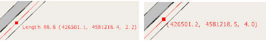
You can also double-click a vertex to open the section dialog and enter the altitude manually. The screenshot below shows a manually entered value of 4m for the point labeled P2.
Exercise 8. Viewing a 3D Animation
Now we can run the simulation to see 3D animation in action.
To view the 3D animation:
-
Right-click on the Replication and select Run Animated Simulation.
-
In the 3D view, zoom and pan around the network and try the different available cameras to view the animation in progress.
Exercise 9. Tracking a Vehicle with a Camera
During a simulation, or playback of a simulation, you can click on any vehicle in the 3D view to place a temporary camera behind it. This camera follows the vehicle through the simulation until it leaves the network.
To track a vehicle with a camera:
-
Run the simulation.
-
Pause when you see a vehicle you would like to track.
-
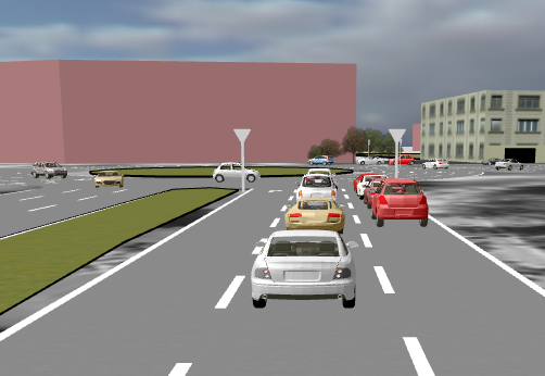
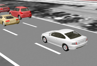
In the 3D view, click once on the vehicle. The camera view will shift to the rear of the vehicle.
-
Restart the simulation. The camera will follow the vehicle.
-
(Optional) Change the camera's relative position to the vehicle by clicking and dragging in the 3D view.
-
You can also press keys 1, 2, 3, and 4 to switch between four predefined positions, illustrated below.
Exercise 10. Creating a Camera Route
In this exercise we will create a bespoke camera route by using a dynamic bookmark in the 3D view. A camera route comprises a series of camera views (or positions) that follow a preset sequence, providing smooth visual coverage of key parts of the simulated network. A dynamic bookmark can accommodate several camera positions and, during simulation playback, the view will follow these positions according to set timings.
Before adding your dynamic bookmarks, play the simulation once or twice and devise a storyboard of the key locations and events you want to include in your visual coverage. Sketch ideas or make notes if it helps.
To create a camera route:
-
Select the 3D view to make sure it is the active view.
-
Zoom or pan the 3D view to the first position in your storyboard (e.g. this could be an overhead establishing shot).
-
Select Bookmarks > Bookmark this Position to save the bookmark and the first position.
-
In the Bookmark Creation dialog, enter a Name for the bookmark and for Type, select Dynamic.
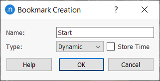
-
Click OK to save the dynamic bookmark.
Now we need to add more positions to this bookmark.
-
Select Bookmarks > Edit to open the Bookmark Editor dialog.
-
Click the dynamic bookmark you just created. Currently it has only one entry in the list of positions in the Dynamic Bookmark Settings group box.
-
In the 3D view, zoom or pan to the second position in your route and, when you are happy with the location, click Add. This adds the second camera position to the dynamic bookmark (and therefore your route). Repeat this step for as many positions as you need to complete the whole camera route.
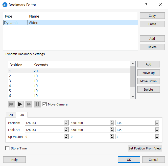
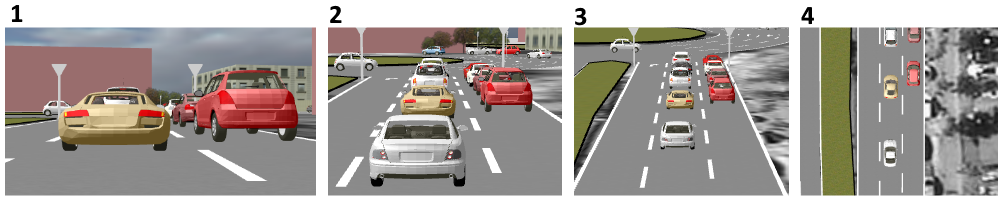
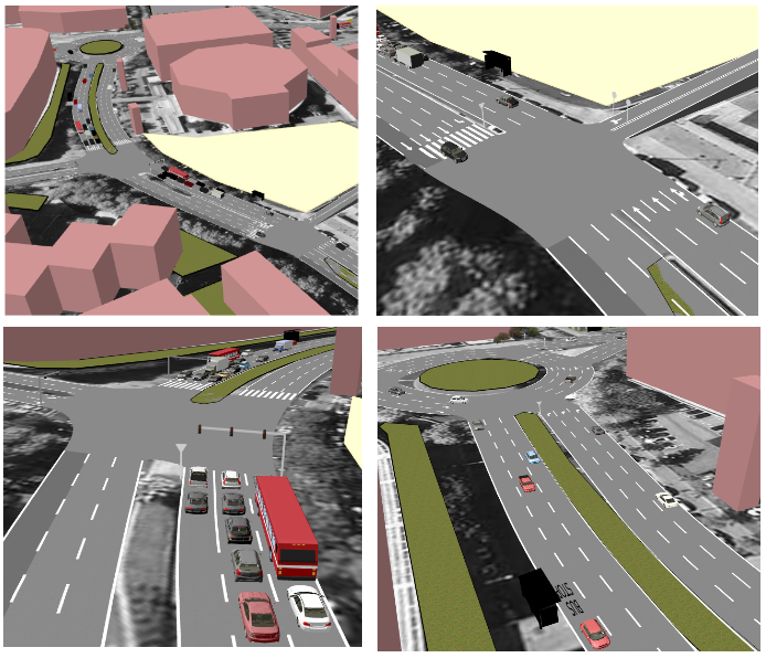
Just as an example, you could save the following four positions, among others.
Note that each Position has a number of Seconds, which is how long it takes to move from one position to the next. To change the number of seconds, double-click in the relevant cell and enter a new value.
-
Click OK to save the dynamic bookmark.
You can playback this camera route at any time.
To playback the camera route:
-
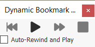
Select Bookmarks > Dynamic: Video to display the Dynamic Bookmark playback control.
-
Click the following buttons as needed:
 Play the camera route in the 3D View
 Jump to the next position
 Restart
 Stop the playback.
 -
Depending on your results, you might like to add or delete position, or change timings.