Transit Vehicles
Transit vehicles are modeled in Aimsun Next by including vehicles in the simulation which follow fixed routes, run to a timetable, use lanes reserved for transit vehicles, and stop at transit stops. Aimsun Next also includes transit in Travel Demand Modeling using static transit assignments and adjustment scenarios to model the demand placed on transit in the traffic network.
A transit line has a route and a set of timetables. Multiple timetables can be attached to a line each with multiple time slices. Time slices control the variation in the departure frequency by time of day, multiple timetables allow different options to be tested different scenarios or the service on different types of day to be programmed (i.e. workday, weekend ...).
Transit routes and timetables are assembled into a Transit Plan which is then linked to a scenario in the project. Different transit Plans with different selection of routes and timetable are in effect the transit options that can be applied to the transport scenarios being tested in the project.
Transit Network
The road network must include provision for transit, specifically the stops where vehicles halt and passengers board and alight, the lanes reserved for transit vehicles and the signal settings which allow them priority at junctions with signal priority.
Transit Stops
Transit stops (for example, bus stops) are the locations along the route at which transit vehicles stop in order to pick up or drop off passengers. Each transit stop belongs to one section, though a section can have several transit stops. However, for a particular transit line, no more than one transit stop can be used in the same section. Different transit lines can use the same transit stop.
Transit stops are described in the Transit Stop section.
Transit Stations
Transit Stations group together several Transit Stops where transfers are possible between the stops. Transit stops are described in the Transit Station section.
Transit Sections and Lanes
Reserved transit lanes can be defined along a transit route. A reserved transit lane is an area of the carriageway reserved for the use of transit vehicles and occasionally other permitted vehicles, for all or part of the day. They allow transit vehicles to bypass traffic queues, usually on approaches to signalized junctions or roundabouts. To define a reserved lane for transit vehicles only, the transit vehicle must belong to the class allowed in the reserved lane and that the reserved lane is defined as ‘Compulsory’.
A road section can be designated as a section, for use by, for example trams. In this case it might be beneficial to show the section as a track rather than as a normal road. The Road Type Editor has options to alter how sections are displayed.
Refer to the Lane Types Section, The description of Road Section Lanes and how to Reserve Lanes for more information.
Transit Signals
Signals can be configured to give priority to transit vehicles as they approach the junctions. Consult the Control Plan Editor Priority Section and Actuation Section
Transit Zones
Transit Zones can be configured to group fare costs in a static transit assignment. Consult the Static Transit Assignment section for more information.
Transit Lines
A transit line is composed of a route, a set of transit stops, and a timetable. Each time interval in the timetable has a program of departure times and the type of vehicle to use e.g. bus, minibus, tram, etc.
A network can contain as many transit lines as required. All the existing transit lines are listed in the Project Window in the Transit Lines folder inside the Transit main folder. The lines are grouped in a Transit Plan which is then included in a scenario.
To create a new transit line, select Project > New > Transit > Transit Line or, in the Project window, right-click Transit > New > Transit Line. The new transit line will be added to the Transit Lines folder in the Project Window in the Transit main folder.
A transit route is a fixed series of consecutive sections through which each transit vehicle of the line will have to pass. Vehicles are created on the first section and removed on the last.
The departure time of transit vehicles along a route is governed by a timetable. This specifies the departure times, where the frequency or the type of vehicle might vary during the day. After the transit vehicle has departed at the time according to the timetable, it stops at the defined stops for a predefined amount of time and it can also be timed to leave intermediate stops along the route at predetermined times. This last option ensures buses adhere to the published timetable independently of traffic congestion and allows passengers along the route to know when they should arrive at a stop in order to catch the service they require.
Transit Line Editor
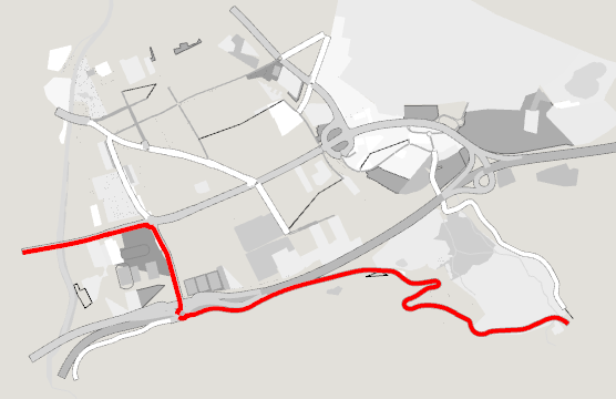
Double-click on a transit Line in the Project window or open its context menu and click on the Properties command to open the Transit Line editor. All the sections composing the line will be highlighted on the network (see the next figure). The selected route will be highlighted in red, the selected section in the route list is highlighted in orange, and the transit stops belonging to the transit line are highlighted in green (using this color ramp ).
Main tab
The Main tab contains the route for the transit line. If a section has transit stops associated with it, then one (and only one) of these stops per section can be associated with the route. Refer to the Transit Stop section for details. Transit lines with no transit stops are also accepted, and in that case transit vehicles will not stop during their trip.
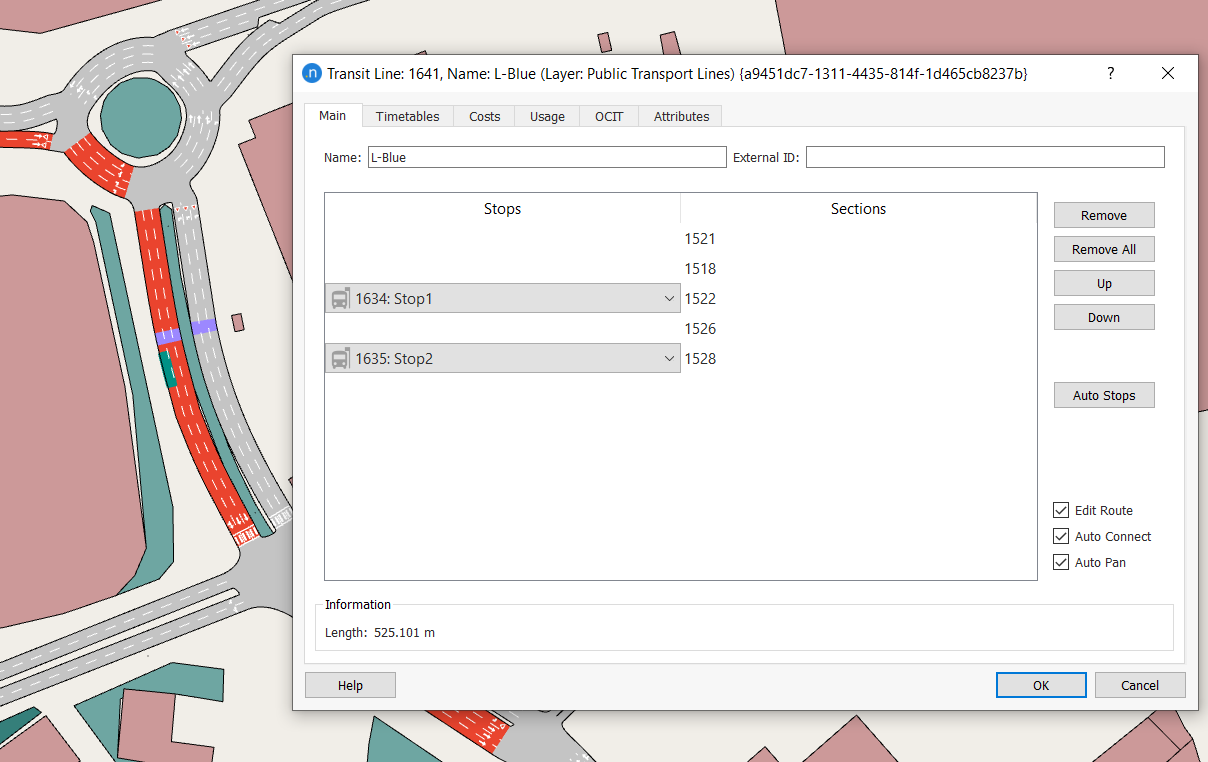
Editing a Transit Line Route
To add sections to the route, ensure the Edit Route checkbox is selected, and click on the sections in the 2D view. Sections are added after the currently highlighted section in the route list. If no section is selected the new section will be added as the last one. When the Auto Connect option is on, the editor automatically connects two unconnected sections using the shortest path (in distance) between the two. It is not necessary to select each section individually, it is only necessary to select enough sections to define the route – which might not be the shortest path – between origin and destination.
If new sections are to be added in the middle of a route, select the preceding section in the editor and click on the 2D view for each new section in the same way as when adding sections to the end of the route.
Pressing the Ctrl key while clicking on a section will add this section before the one selected in the list. If no section is selected, the section will be added as the first one.
The Delete All button will completely erase the route, while the Delete button will erase just the currently selected section from the route. To change the order of sections in a route, select a section and use the Up and Down buttons.
If the Edit Route toggle is checked, sections will be added when selected in the 2D view. If the Edit Route toggle is not checked then selecting a section in the view selects the section ( assuming it is part of the route) in the dialog.
The option Auto Connect helps the editing task by automatically connecting two unconnected sections using the shortest path (in distance). Also, if the geometry of the network has changed and a section used by a line has been deleted, this option will then reconstruct the transit line if a connection can be found.
The Auto Pan will pan the view to the selected objects if toggled on.
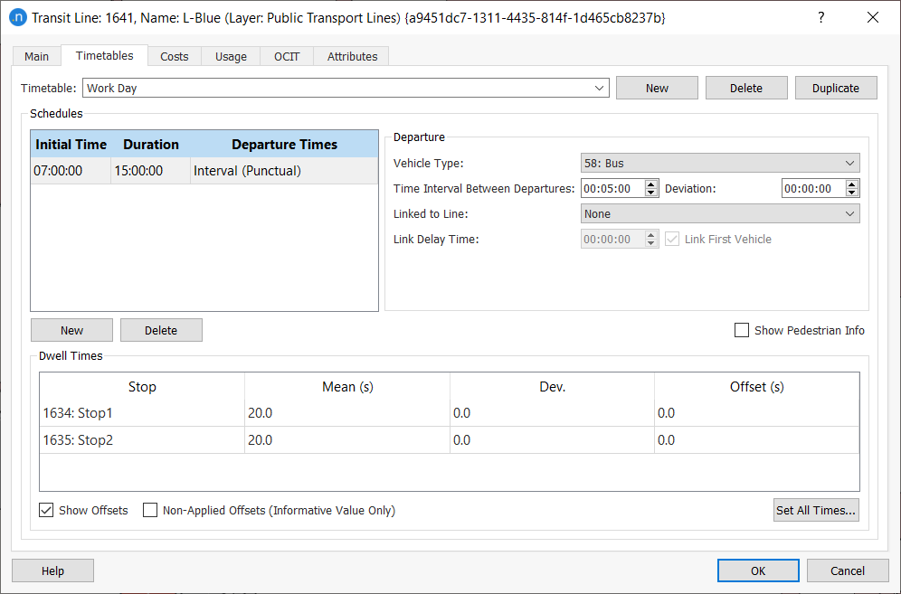
Timetables Tab
A Timetable consists of a set of Time Slices, each one describing the Transit Vehicle's Departure Schedule and the Dwell Times (time the vehicle remains stopped) at each transit stop allocated to the line.
Each Schedule has an Initial Time and a Duration to define the interval when the transit vehicles will be generated using that schedule. Multiple schedules allow for programming a timetable with for example departures every 20 minutes in the off peak period and every 10 minutes in the peak period.
The Transit Vehicle Departures Schedule can be defined in terms of Departure intervals or by a set of Fixed Departure Times. In all the cases, the Deviation value will be used as standard deviation to sample the transit vehicles departures from a Normal Distribution.
Departure Types
The departure types are:
-
Interval (Punctual): This type of schedule is selected when transit vehicles are generated periodically at regular intervals for the time interval of the selected slice. This regular interval is defined as the frequency of vehicle departures based on the time defined. To define this, the time interval between departures and the standard deviation from that value must be specified. If, for example, a time interval of 5 minutes with a deviation of 1 minute has been defined, the departure time will be at 5 minutes (plus/minus the deviation), at 10 minutes(plus/minus the deviation), at 15 minutes, …
-
Interval (Cumulative): This type of schedule is selected when transit vehicles are generated periodically at regular intervals for the time interval of the selected slice. This regular interval is defined as the frequency of vehicle departures based on the time of the previous departure. In order to define this, the time elapsed from previous departure and the standard deviation from that time must be specified. If, for example, a time interval of 5 minutes with a deviation of 1 minute has been defined, the first departure time will be at 5 minutes (plus/minus the deviation). The next will be at 5 minutes (plus/minus the deviation) after this departure, thus the error in departure time is cumulative over the schedule
-
Fixed: The third option is to create a list or timetable with a set of predetermined departure times for each vehicle. This also includes the standard deviation from that departure time, as in the other schedules. This option provides for irregularly timed departure schedules.
Vehicle Type
The Vehicle Type list is used to define which of the vehicle types in the model is to depart at the selected times. If the Schedule Interval is defined, all vehicles will be of the same type for the entire slice. If the Fixed Schedule is defined, a different vehicle type can be associated with each departure.
Linked to Line
The Linked to Line parameter provides a precondition when generating a vehicle on a line, linking it to the arrival of another transit vehicle during the simulation. Before a new vehicle is generated for a line whose departure has been set as linked, it will check whether a vehicle from the line to which it is linked has arrived after the departure of the previous vehicle from the current line).
If the Interval Schedules are being used, all vehicles on the edited line will be linked to the other line. If a Fixed Schedule is being used, not all departures have to be linked, only a selected subset need to be linked. In this case, Aimsun Next will check if a vehicle from the linked transit line has arrived in the period since the last linked departure from this line.
Also, in order to simulate the time passengers require to move from one transit line to the other, a Link Delay Time can be specified. This will delay the departure of the second vehicle after the arrival of the first one. Linked behavior can be specified to start at the second vehicle in the simulation by toggling the ‘Link First Vehicle’ option off. This is useful when modeling circular lines, as then the first vehicle will not have to wait for any other vehicle to arrive.
Stop Times
For each transit stop along the route, the mean stop time and a deviation are defined. This is the time that the transit vehicle will remain stopped at each transit stop and is also sampled from a normal distribution. This is used to simulate the passenger boarding and alighting times; different passenger rates are simulated by programming transit vehicles to wait for a suitable length of time at each stop.
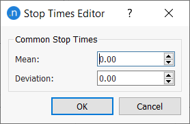
The Set All Times... button opens an editor that allows a mean time and a deviation to be applied to all the stops in the line.
If the Show Offsets option is checked, an offset at each stop can also be defined. The offset is used to set expected times at intermediate stops. This value sets the number of seconds from the departure time at the beginning of the line of the transit vehicle to the time when the vehicle is expected to be at this stop. If the traffic conditions allow the vehicle to get to the stop earlier than expected, then it will wait until the expected time has elapsed. The transit vehicle cannot leave the stop before the offset time has elapsed, but it can leave later than the offset if it experienced a delay because of the traffic conditions. If the Offsets are to be used for information only, i.e. to report on transit punctuality or used by an API module, then the Non-applied Offsets (Informative Value Only) option should be ticked.
Costs tab
On this tab, both Boarding Fare (access) and Distance Fare (in-vehicle) can be specified. These values are taken into account by the Boarding Cost Functions described in the Transit Assignment module.
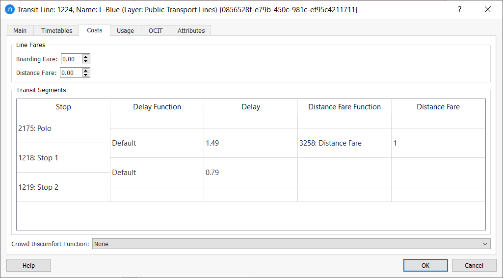
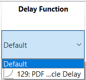
You can also select the transit Delay Function and the transit Distance Fare Function per segment from transit stop to stop here. Alternatively, you can input these functions in the Transit Segments table.
Note: If you do not select a delay function, a default value is used, accounting for the travel time in minutes, based on an assumed transit vehicle speed of 20km/h.
If a transit line is based on a fixed schedule timing and the time from stop to stop is known, this information is input by filling in the offsets for each schedule. In the Transit Delay Function, this data is accessed through the scripting function getTimeTableStopToStopDelay.
A crowding discomfort function for this transit line can also be specified to quantity the perceived increased cost in traveling on a busy transit vehicle. This is documented in the Function Editing section.
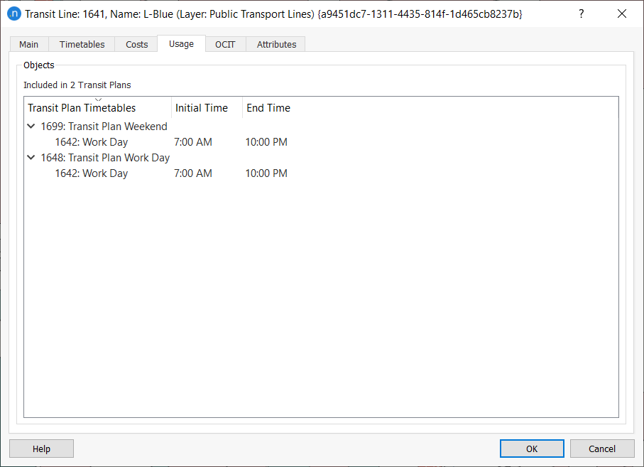
Usage Tab
The Usage tab shows which Transit Control Plans include this transit line. The expand toggle provides details of the activation time(s) for each plan.
OCIT Tab
The OCIT tab provides data about the transit line in OCIT (Open Communication Interface for Road Traffic Control Systems) format. The OCIT data is used in communications between central traffic control and information systems.
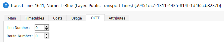
The OCIT information is used in the Sitraffic Controller and the VS-PLUS Controller.
Transit Zones
Transit zones are collections of transit stops which share a fare cost between them. Fares can be interzonal, between zones, or intrazonal for trips within a zone. For example a city with fixed charge for all transit trips within the city might have all its transit stops in one zone, but if it charged a premium fare to reach the airport, that stop would be in a separate zone. Similarly an urban metro line might have a set of concentric zones with different fares applied to trips within the city center and trips that traveled into the city center.
A network can contain as many transit zones as required. All the existing transit zones are listed in the Project window in the Transit Zones folder inside the Transit main folder. The zones are grouped in a Transit Zone Plan.
Transit Zone
A transit zone is composed of a set of transit stops.
To create a new transit zone, select New > Transit > Transit Zone or, in the Project window, right-click Transit > New > Transit Zone.
The new transit zone will be added to the Transit Zones folder. Also, the new transit zone will be assigned to the current active Transit Zone Plan. If there is no transit zone plan, a new one will be created. The zone editor can then be used to add transit stops to the zone.
In the 2D map, the new transit zones are included in the Transit Zones layer, which is a sub-layer of the Transit Network layer.
The zone plan is then available to be selected in the Transit Assignment Scenarios.
Transit Zone from a Polygon
The alternate option to create a transit zone is by converting a polygon to a transit zone.
First create a polygon that encloses the target transit stops. Refer to the Polygon Graphical Editing section for details on creating a polygon.
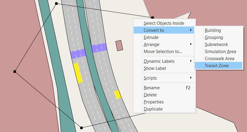
Once the polygon has been created, it can be converted to a transit zone by right-clicking on the polygon selecting Convert To > Transit Zone, as shown below.
A new transit zone will then be added to the Transit Zones folder and it will be assigned to the active transit zone plan.
Transit Zone Editor
Double-click on a transit zone in the Project window or open its context menu and click on the Properties command to open the Transit Zone Editor. All the transit stops composing the transit zone will be highlighted in the network.
Main tab
The Main tab contains the transit stops that form the transit zone.
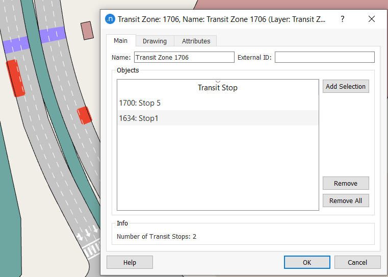
To add new transit stops, click on the stops in the 2D view and click the Add Selection button. Stops can be selected individually or, if multiple stops have been selected, all are added to the zone. Only the stops that not belong to the zone yet will be added in the list.
To remove one transit stop, select the stop in the list and click the Remove button. To remove all the stops in the list click the Remove All button.
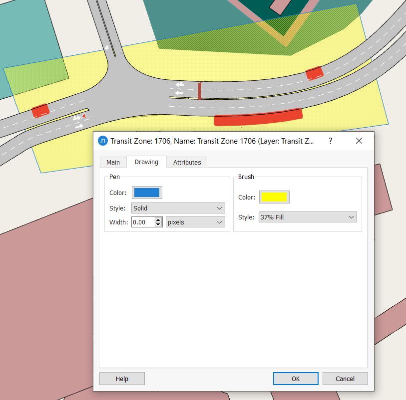
Drawing Tab
The Drawing tab is used to edit the 2D attributes of the polygon that forms the transit zone. The border line and the area fill can be specified. If the zone was created by selecting individual stops, no polygon is available and there is no visualization for the zone.
Transit Zone Plan
A transit zone plan is composed of a set of transit zones and a fare matrix that defines the cost of traveling from one zone to other zone (or the same one).
To create a new transit zone plan, select New > Transit > Transit Zone Plan or, in the Project window, right-click Transit > New > Transit Zone Plan.
Transit Zone Plan Editor
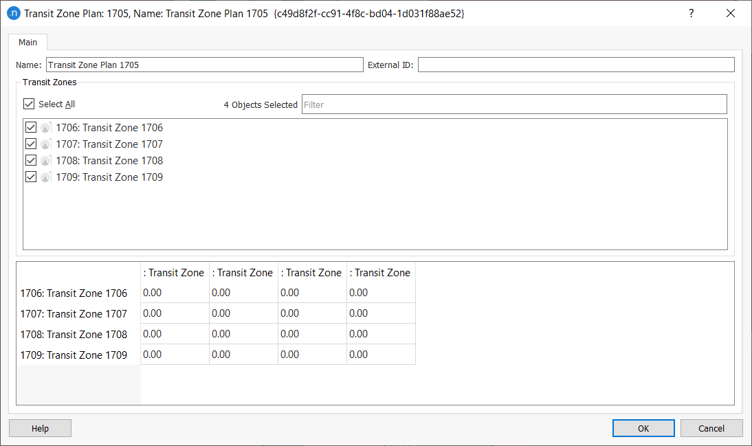
Main Tab
The Main tab contains the selected transit zones and a matrix for defining the fare costs between zones.
Editing a Transit Zone Plan
To add or remove a transit zone check it in the list. This action will modify the Fare matrix adding/removing the row and column that refers to the target transit zone.
To define a fare cost between two zones, set the fare in the corresponding cell of the matrix Note that rows are origins and columns destinations.
Active Transit Zone Plan
More than one transit zone plan can exist in the same network but only one can be active in the visualization.
The active transit zone plan is marked in the Project Window with a blue icon. Inactive Zone Plans are marked in gray. A transit zone plan can be activated by right-clicking on it in the Project Window and choosing the Activate option. The previously active transit zone plan will automatically be deactivated.
When a new transit zone is created, it will be assigned to the active transit zone plan, or the first plan is generated in the project. The fare costs concerning the new transit zone are initialized to 0.
Recalculate Transit Zones
Transit zones can be visualized in the main 2D view as polygons if they have been created as polygons. Other transit zone created by individually selecting stops will not be able to be visualized initially. The Recalculate Transit Zone Plan option is used to calculate the transit zone polygons taking into account the distances among the stops defined in each zone.
To recalculate the transit zone polygons that belongs to a specific transit zone plan, select the Recalculate Transit Zone Plan option in the target transit zone plan's context menu.