Control Plans
A Control Plan specifies the control parameters applied to a set of junctions and meterings in a network, starting at a specified time. Each junction can have its own set of actions with phases, timings, offset, and cycle time specific to that junction. A collection of signal control parameters for a number of junctions and/or meterings forms a Control Plan.
Editing
The editing order for control plan data is:
- Create and edit the Control Plans that will be used.
- Create a new Master Control Plan and assign the Control Plans to it.
When microsimulation, mesoscopic simulation or a hybrid simulation is to be used:
- Assign the Master Control Plan to a scenario.
Junctions
The main parameters for a junction are:
- Control type: unspecified, uncontrolled, fixed control, external or actuated.
- Offset: used to set the beginning of the sequence of phases regarding to the control plan's initial time, and therefore synchronize adjacent junctions within the same control plan.
- Phases: determine the different time periods of green signal activation.
Metering control parameters depend on the type of metering and are discussed in the section concerning Metering Control.
Control Plan editor
Creating a new Control Plan
To create a new control plan select the New…/ Control / Control Plan option either in the Project Menu, in the Project window Control folder context menu or in the Project window Control Plan folder context menu. Once done, the new control plan will be added to the Control Plans folder in the Project window.
Open the control plan editor by double-clicking on the control plan in the Project window.
Use the Rename option in the Control Plan’s context menu to rename it, or rename it in the control plan editor.
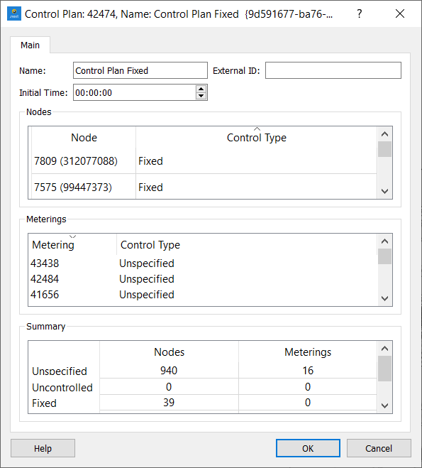
The Initial Time at which this control plan starts can be defined here. It is the absolute time at which the nodes group of phases will be set at time 0.
The Initial Time does not have to match the time at which the Control Plan will be set to start in the Master Control Plan. The Control Plan will be applied in any case taking into account its Initial Time. So, for example, if the Initial Time is set to 00:00:00, the cycle on one node is 110 seconds and the Master Control Plan states that the Control Plan is applied from 08:00:00, then at 08:00:00 the Control Plan in that node will be at second 90 of the cycle ( 8x60x60 sec/110 sec = 261 complete cycles + 90 sec).
A list with all the nodes in the network and the control type associated with each of them is shown. When the control information has not been specified in a node, the control type is set to Unspecified. Otherwise, the control can be Uncontrolled, Fixed, External or Actuated.
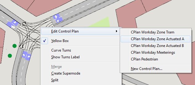
To specify the control information in a node, double-click on the desired node in the node list or right-click on the node in any 2D view and select Edit Control Plan and the control plan. The Control Plan editor for the node will open.
A list with all the meterings in the network and the control type associated with each of them is also shown. As with nodes, when the control information has not been specified in a metering, the control type is set to Unspecified. Otherwise, the control can be Uncontrolled, Fixed, Actuated or External.
To specify the control information in a metering, double-click on the metering in this editor’s metering list or right-click on the metering itself in any 2D view and select Edit Control Plan and the control plan.
A Summary table shows how many nodes and meterings there are for each control type.
Control Plan Editor for Nodes
Use the Node context menu to open the editor for the chosen control plan. If there is no control plan, a new one can be created from this menu.
The Control Plan editor, in the Project window, can also be used to open the control plan from a particular node by double clicking on the node in the list.
Five different node types are available:
-
Uncontrolled: Node managed by stops and yields. The traffic lights, if any, are disconnected.
-
Fixed (or pre-timed): Node managed by traffic lights with fixed green lights. Different control plans can be assigned to different time periods, to simulate the change of timings depending on the time of day.
-
Actuated: Traffic control system that follows the NEMA (National Electrical Manufacturers Association) standards. For further details on these standards, please refer to NEMA Standards Publication TS 2-2003 v02.06 Traffic Controller Assemblies with NTCIP Requirements.
-
External: The controller follows pre-timed control but can be combined with an external control policy implemented using the Aimsun Next API.
-
Unspecified: A node with no control plan information defined. This type is used when working with different zones to let the simulator know that the control plan for the previous zone is still in use.
The Offset parameter is used to synchronize adjacent nodes (know as a "green wave"). It formally specifies the displacement that is applied to the node cycle when the control plan is initialized (e.g. an offset of -3 means that at the beginning of the control plan, the state of the traffic lights at this node will be that defined for the third second in the node control plan).
The specified Yellow Time (or Amber Time) is not inserted between one phase and the next but replaces the first seconds of the red phase. This means that if, for a certain turn movement, its green phase is assigned 34 seconds and the rest of the cycle lasts 66 seconds, then specifying a 4-second Yellow Time will model that traffic light as: 34 seconds of green light plus 4 seconds of yellow light plus the remaining 62 seconds of red light.
The behavior of vehicles at a yellow light has two phases, depending on the Red Percentage that is defined. Red Percentage indicates the percentage of yellow time that vehicles will consider as red time.
The first phase is the percentage of the yellow time (i.e. 3 seconds in the case of a 4-second yellow that has a Red Percentage of 25%) when drivers consider the yellow time to be basically the same as green time (so they proceed).
During the remaining portion of the Yellow Time (i.e. 1 second in the case of a 4-second Yellow Time with a Red Percentage of 25% as described above), vehicles apply a normal braking rate instead of the maximum rate they could reach under a red light.
As an example, in the illustration below the Red Percentage is set to 60% and so vehicles consider 40% of the Yellow Time to be green and 60% to be red.
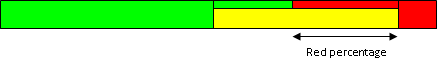
Note: Pedestrians at signals on crosswalks also use these percentages on a flashing Don't Walk signal when they decide to cross or wait at the signal.
Traffic signal modeling in microsimulation is implemented using fictitious stopped vehicles, which are created and located at the stop line when the light turns red and eliminated when it turns green. In this way, the car-following model can be used to model braking to stop in front of a red light. If there is non-zero yellow time, the fictitious stopped vehicle will be created when the remaining yellow time corresponds to the specified red percentage.
The yellow time defined for the node can be overwritten at the phase level specifying a different yellow time for the desired phase. The yellow time at a phase applies to movements becoming red when that phase becomes green. Then, for example, a yellow time on an interphase will apply to the movements that were green in the previous phase and that turn to red in the interphase.
It is possible to specify a yellow time for the red to green transition for fixed control plans. If a value greater than zero is specified for this yellow time, the reaction time at traffic light will start to be taken into account from the beginning of the red-yellow state and the vehicle will start moving at the latest between the start of red-yellow + reaction time at traffic light or the start of the green.
The Rest in Red parameter is only necessary for actuated control and consequently it will only appear when the control type is defined as Actuated.
When the type is External, there is a critical checkbox option used to mark those nodes that might receive preferential treatment in a given external adaptive system. This parameter is only considered when the simulator is connected to an external adaptive control system that requires it as input.
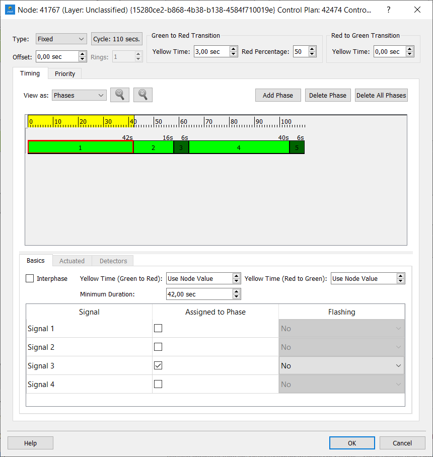
Clicking the button where the cycle length is shown opens a dialog where the cycle duration is defined in seconds.
Timing tab
In the Timing tab, the different phases of the intersection cycle are defined. A Phase is defined as a time period for which there are no changes in the state of the traffic lights at that node.
The timing defined can be viewed as Phases or as Signal Groups. When viewed as Phases, in the timing diagram the different phases defined are drawn. When viewed as Signal Groups, the phases visualization will change to a signals visualization where the green and yellow times for each signal can be seen.
Phases are built as follows: first the phase is created by clicking on the Add Phase button; then it is modified by adapting it in the timing diagram to its desired start time and duration and finally selecting the signal groups (each active signal group enables its associated turns) as being active (green) during that phase.
When making a phase longer by dragging its border, the neighboring phase is shrunk if necessary. If the drag is to the right, and the [Ctrl] key is pressed the cycle time will grow instead, maintaining the duration of the following phase.
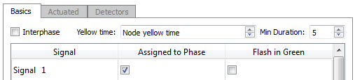
The signal groups are listed in the Basics subtab; they are selected by ticking the Assigned to Phase column on the desired signal group.
The Flashing column has three different options:
- Green: only for display purposes, the traffic light will flash in green color during the green time of the phase, then change to yellow, or red if there is no yellow time defined.
- Yellow: vehicles will apply a yield behavior at the end of the section before taking the turn; the traffic light will be displayed in flashing yellow during the green time of the phase, then change to yellow, or red if there is no yellow time defined.
- Red: vehicles will apply a stop behavior at the end of the section before taking the turn; the traffic light will be displayed in flashing red during the green time of the phase, then change to yellow, or red if there is no yellow time defined.
The Interphase parameter located in the Basics subtab is an optional type of phase to model the fixed clearance time in between phases. This type of phase is then set between phases. For instance, an intersection with a 60-second cycle and two equally important movements (symmetric distribution of time), could be modeled with:
- 2 phases with a duration of 24 seconds
- 2 interphases (each interphase in between the two phases) with a duration of 6 seconds
- 3 second yellow time (either at the global level for the node or at the interphases)
This would produce 24 seconds of green light, 3 seconds of yellow light and 3 seconds of clearance time plus 30 additional seconds of red light (that is a total of 33 seconds of red light) for each one of the movements.
In Fixed Controls, a Minimum Duration field, taken into account for Priority calls, will be shown. For External Control, the Minimum Duration and Maximum Duration fields are available.
Finally, the yellow time for a phase can be defined as a global one defined for the node or as a different specific value, applied to the movements changing to red when the phase being edited begins.
When a phase is selected, the allowed turns, that is, the turns associated with the active signal groups, are drawn in the active 2D view in the primary mark color.
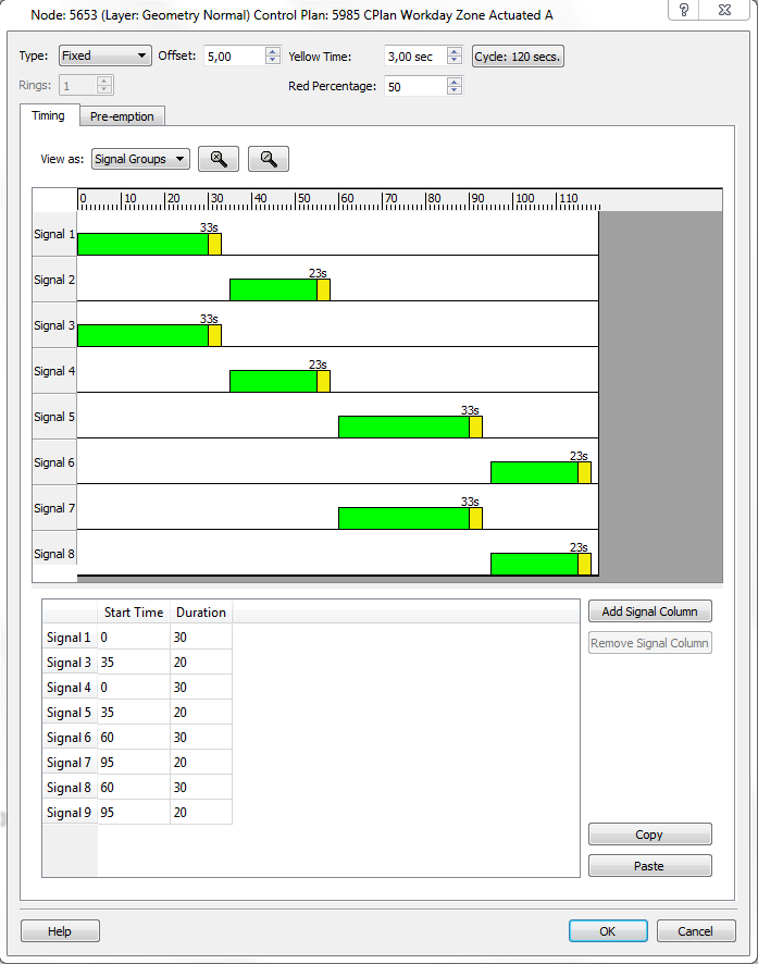
When the Control type has been set to Fixed, and the timing is set to be viewed as Signal Groups, it enables a different way of defining the control plan. This method bypasses the need to define Phases and consists of defining Start Time and Duration for each signal group. The buttons Add Signal Column and Remove Signal Column can be used to add or remove a pair of columns to the right of the table so more than one Start Time-Duration pair can be inserted per signal group.
When the Control type has been set to Actuated or External, a Minimum and Maximum Duration for each phase can also be specified. For further details on the Actuated and Detectors please refer to NEMA Standards Publication TS 2-2003 v02.06 Traffic Controller Assemblies with NTCIP Requirements.
Signals Groups and Phases
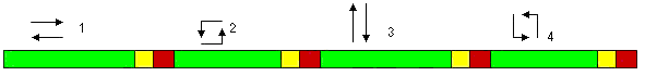
For intersection control, a phase-based approach is applied in which the cycle of the intersection is divided into phases, where each phase has a particular set of signal groups with right of way at the same time. The units for defining the phases of a control plan are seconds. The duration of a phase determines the duration of the green time of the signal groups assigned to the phase. The following figure shows an example of signal groups for a simple intersection.
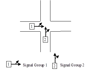
A signal group consists of the set of turn movements that are controlled by the same indications of traffic lights. Therefore, the signalized movements that have right of way simultaneously can be grouped into one signal group. A sequence of phases is then defined for the whole intersection where each phase has a set of signal groups associated with it.
The previous figure shows an example of a right of way sequence for a junction, while the next figure shows phase modeling and signal modeling for the same junction.
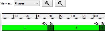
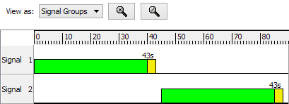
In the example, there is a first phase during which turn movements belonging to signal group 1 have a green light. Second, there is a clearing phase when no movement is allowed. The third phase gives right of way to the movements associated with signal group 2, while the last phase is again another clearing phase.
Several signal groups can be defined for the same turn if specified for different vehicles classes. Each signal group can also have a different stop line, that is, the distance from the intersections where vehicles belonging to that vehicle class will stop.
During the simulation of a scenario, Aimsun Next will execute a control plan taking into account the phase modeling for each node. However, this control definition can be variable over the simulation period. Different plans can be deployed that will be activated during the simulation at the specified time.
Additionally, an External Traffic Control and Management System (ETCMS) can modify this execution by means of different actions, such as changing the duration of a phase or jumping directly from one phase to another. ETCMS interfacing is available via the Aimsun Next API Module, explained in detail in the API Section of the Manual.
At any point during a simulation it is not possible to modify the traffic control plan structure (i.e. the definition of signal groups), but it is possible to change the allocation of signal groups to phases or the duration of any phase. Changes will only apply to the following simulations, though, not to the current one.
Conflicts between turn movements belonging to the same group might arise in the context of an intersection, such as turn while the opposite through traffic stream is also crossing. For this purpose, it is possible to define a yield or stop sign for the lower priority turn movements, so they will have to yield to those with higher priority.
The Mesoscopic simulator models the traffic signals by using events that lets or forbids vehicles to enter into the junction. When the traffic light is changed to red all vehicles waiting to enter into its downstream junction are not allowed to do the movement. When the traffic light is changed to green then the node server looks for the next vehicle that can enter into the junction considered the new permitted movement.
Priority tab
The priority tab is used to edit the strategies used to trigger stage changes as Transit vehicles approach a junction.
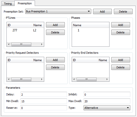
If there are several phases in a node that could receive priority on request, a different priority Set must be configured for each one. After adding a new set of priorities with the Add button, the following parameters must be filled in for its definition:
-
Transit Lines: This is the list of Transit Lines that activate a priority request for the dwell phase. The request for priority is emitted if the transit vehicle crossing the correspondent detector belongs to one of the listed transit lines and is equipped. The percentage of equipped vehicles is set in the Vehicle Type editor.
-
Dwell Phase: The requested priority phase, which gives right of way to the emitted priority request.
-
Detectors Priority Request: List of detectors that activate a priority request. The Equipped Vehicle capability must be active for all the detectors in this list. When an Equipped Transit vehicle belonging to one of the defined transit lines crosses the detector, a priority request for the dwell phase is created.
-
Detectors Priority End: List of detectors that make the priority request end. All the detectors in this list must have the Equipped Vehicle capability active. When an Equipped Transit vehicle belonging to one of the defined transit lines crosses the detector, the priority request for the dwell phase will end, as long as the Min Dwell duration has already elapsed (otherwise the Dwell phase will end when the Min Dwell is over).
-
Delay: Time elapsed, in seconds, between the moment that the transit vehicle is detected (by one of the detectors defined in the list of Priority Request Detectors) and the moment that the corresponding request is activated.
-
Inhibit: This parameter is only used in combination with actuated control and cannot exceed the value of delay. It defines a time interval (in seconds), at the last part of the priority delay interval, when calls from other actuated detectors will not be taken into account.
-
Min Dwell: Defines the minimum duration of the Dwell phase.
-
Max Dwell: Defines the maximum duration of the Dwell phase. The dwell phase will always end either because maximum dwell has been exceeded or because one of the Priority End Detectors has detected the transit vehicle in question, whichever happens earlier.
-
Reserve: Defines the time (in seconds) after the end of a dwell phase during which any additional priority requests will be ignored. This is used to prevent frequent priority services. By default, for any additional transit vehicles detected while the dwell phase is active, no priority requests will be made. This is regardless of the value of "reserve".
-
Type: Sets the algorithm to be used: Serve All or Alternative. Serve All serves all the remaining phases between the current green phase and the dwell phase with their minimum green time. The Alternative serves the dwell phase as soon as possible, after the minimum green time of the current green phase and interphase if applicable.
For Fixed Controls, the transit priority logic will make use of the Min Duration parameter set for each phase in the Basics folder. For any phase that has green time between the moment when the priority is requested and the dwell phase gets green, after its minimum duration is over, the phase will become red.
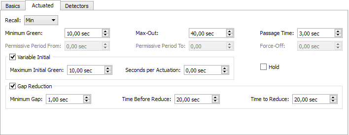
Actuated Parameters
-
Minimum Green: The shortest green time initially assigned to a phase. A phase will always stay green for at least the Minimum Green seconds specified. If an Extensible Initial method is chosen, then the parameters Maximum Initial Green and Seconds per Actuation also need to be defined.
-
Variable Initial (or Extensible Initial): method that calculates the initial green time depending on traffic demand that has arrived during the previous yellow and red time. This Variable Initial Green Time consists of adding to the Minimum Green the time obtained from multiplying the Seconds per actuation by the number of vehicle actuations recorded during the previous yellow and red signal periods for this phase, up to a Maximum Initial Green time. To enable this volume-density feature, it is necessary to use locking detectors and it is also necessary for detectors to have count as one of their measure capabilities. (The extensible initial method is not taken into account when running a mesoscopic simulation).
-
Maximum Initial Green: The maximum value up to which the initial green time can be extended when an Extensible Initial method is used.
-
Seconds per actuation: This is the number of seconds the Minimum Green is extended for each actuation taking place when an Extensible Initial method is used and while that phase is not active, .
-
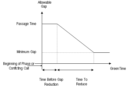
Allowable Gap: The minimum time difference between detector actuations. When initial green time is over, if time between two actuations is less than the allowable gap, the active phase will be extended for allowable gap seconds. When the time between actuations exceeds the allowable gap, the active phase will end by Gap-Out. The allowable gap coincides with the Maximum Gap in the case where no Gap Reduction is applied. If a Gap Reduction function is active, the allowable gap can change over time taking values from Maximum Gap down to Minimum Gap.
-
Passage Time or Maximum Gap: The maximum allowed time difference between detector actuations. It is typically set to the Passage Time (time to reach the stop line from the detector) in the case of detectors located at a distance from the stop line. For the case of presence detectors located close to the stop line, it is typically set to an acceptable headway between vehicles.
-
Minimum Gap: The value to which the allowable gap will be reduced when using a Gap Reduction feature.
-
Gap Reduction: Gap reduction is a process that reduces the allowable gap from the Passage Time down to the Minimum Gap. This reduction process starts after a specified time (Time Before Reduce) that extends from the beginning of the current green phase or from a call to service from a conflicting movement (whichever occurs later), to the time that the gap reduction process begins. The gap is reduced from the passage time to the minimum gap, over a specified amount of time (Time to Reduce). The next figure depicts the allowable gap during the green time.
-
Maximum Green Time or Max-Out: States the limit up to which the green time can be extended in a phase. When the green phase extends to this maximum limit, then the phase is said to terminate by Max-Out. The Maximum Green Time is held until a conflicting call is detected. When a conflicting call is received it starts timing down.
-
Recall: Activates the specified phase. The available options are:
- No Recall: An actuated phase with no recall will only be activated by a call; if not called (if no demand has been detected), it will be skipped. Once the phase is active, it can be extended based on vehicle demand. The phase will end by Gap-out or Max-out.
- Minimum Recall: The phase will be activated at least to its Minimum Green value even in the absence of an actuation (i.e. pedestrians are not detected but nevertheless are guaranteed enough crossing time). It can be extended based on vehicle demand and ends by Gap-out or Max-out.
- Maximum Recall: A constant vehicle call is applied to the phase; it extends to the Maximum Green (Max-out).
- Coordinated Recall: The coordinated or "synch" phase (see next point) will be activated every cycle. Its duration to the yield point will include any unused time from preceding phases. In the presence of a coordinated phase, the offset is set with respect to this phase instead to the first phase.
-
Rest in Red: This feature keeps all the signal indications in red in the absence of a call. Then, the phase receiving the first call will be directly activated, with no clearance interval required.
- Hold: If a phase has this feature activated, the current green interval is retained until it yields to a conflicting call. It is the opposite command to Rest in Red.
Coordination Parameters
Without signal coordination, the cycle duration varies constantly depending on fluctuations in traffic demand. Coordinated traffic signal operation requires a fixed cycle length for each timing plan so that it is possible to synchronize a system of interconnected signal controllers. The parameters or elements that define a coordinated system are:
-
Coordinated phase: The coordinated phase is activated each cycle without reliance on detector actuations. This phase duration includes any unused time from preceding phases and stays green until the yield point is reached.
-
Yield Point (or Local Time Zero): The point in the signal cycle that represents the end of the coordinated phase minus the force off defined for the coordinated phase (which by default always is 0). The yield point of all controllers in the network are used in co-ordination. All times in a controller are referenced to the yield point.
-
Force Offs: For each phase there is a point in the cycle, called force-off, at which the phase must terminate at the most, in order to maintain a fixed cycle (the force-off of the coordinated phase is 0 by default). Each force-off point must be computed so that the change period, consisting of the yellow time and all-red time plus the minimum durations of all subsequent phases can be completed before the yield point. The all-red period is the intersection clearance time where the traffic lights are red for all movements.
-
Permissive Period: For an actuated non-coordinated phase, this is the time interval, referenced to the yield point, during which the controller can activate that actuated phase.
-
Offset: The number of seconds from the beginning of the control plan to the yield point, when the parameter "Match Offset with" is defined as "End of Phase". Otherwise, with the "Beginning of Phase" option, the Offset determines the time difference from the beginning of the control plan to the initial time of coordinated phase (yield point minus the maximum duration of the coordinated phase).
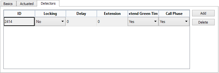
Detector Parameters
One of the advantages of actuated control is its ability to adjust signal timing parameters based on detector actuations that represent current vehicle demand. The detector parameters that control signal timing are:
-
Locking/Non-Locking: The Locking mode retains the number of vehicle actuations until the appropriate phase receives the green interval. This detector counts vehicle actuations during the yellow and red time of the phase (to accomplish this, the detector must have been configured with the count capability), for example for extending the minimum initial green time. This is particularly useful when the detectors are located remotely. The Non-Locking mode retains calls only while vehicles are in the zone of detection (The detector must be configured with presence capability). Non-locking mode is typically used with detectors close to the stop line. For volume-density operation, the locked mode must be selected.
-
Delay Detector: The detector delays its call for an amount of time following a vehicle actuation. This is used in non-locking mode when the desired effect is to produce a signal as if the detector was in a position closer to the stop line.
-
Extension Detector: The detector extends the call for an amount of time. This is particularly useful for very short-call detectors. This is used in non-locking mode with those narrow detectors for which the desired effect is to produce a presence signal as if they were longer.
-
Extend green time: When set to Yes, the detector call is considered when the phase associated with the detector is the one being served.
-
Call phase: When set to Yes, the detector call is considered when the phase associated with the detector is not the one being served.
Multi-Ring Controller
A ring consists of two or more sequentially timed conflicting phases that propagate in an established order. A controller might have a single ring or multi-rings (see next figure).
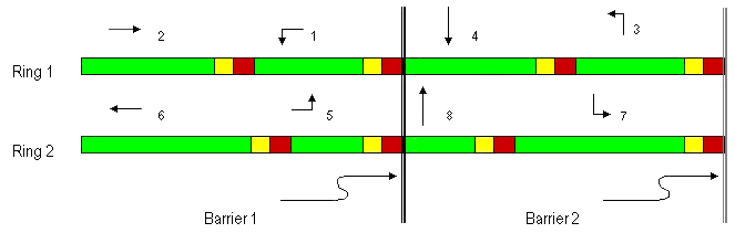
In multi-rings, barriers are those reference points in the sequence of phases at which all rings change from a group of concurrent phases to another one. Barriers assure that conflicting phases in different rings will not overlap. All rings cross the barrier simultaneously and start at the same time the selected set of phases on the other side of the barrier.
There are two modes of operation in multi-ring controllers:
- Single Entry; A mode of operation in which a phase in one ring can be activated alone if there is no call in a non-conflicting phase on any other ring.
- Dual Entry: A mode of operation in which one phase in each ring must be activated when the barrier is crossed. If a call does not exist in one of the rings when the barrier is crossed, then a default phase is selected in that ring.
Rings and Barriers
When the control plan for a node is set as Actuated in the Node editor, the first phase added (by clicking the Add Phase button in the Phases folder) will be added to the first ring and first barrier.
Use the Rings spin box to set the number of rings. Reducing the number will remove the last ring or rings.
To add phases to a ring, the ring must be selected first (by clicking on its name), then press the Add Phase button.
When defining a multi-ring (when a second ring is added), the Single Entry box appears on the top of the editor. Select if Single Entry is the mode to be used by checking the Single Entry box, otherwise the Dual Entry mode be applied. The Dual Entry mode requires a Default phase to be defined for every barrier, in every ring. Default phases are defined with the rest of Actuated attributes of the phases, see the Actuated Phase Editing section.
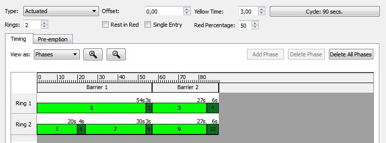
For multi-rings, barriers are added by dragging to the desired time instant the vertical line at the right of the Barriers bar (in gray) in the phases graphical editor, that is, at the end of the control cycle. In the next example the line defining the first barrier was located at second 90 and has been moved to second 50.
Phases Definition
Each phase in an actuated control definition normally includes the green interval plus the yellow time and the following all-red time interval (for each ring independently in case of multi-rings). This phase definition generates two phases in Aimsun Next , one related to the green time and the second one related to the yellow time and the following all-red interval defined as an interphase.
The definition of the actuated control in Aimsun Next is phase oriented, that means the control is defined as a set of different phases with their attributes.
The phase attributes could be grouped in:
- Basic Phase editing
- Actuated Phase editing
- Detector Phase editing
These folders are editable when a phase is selected in the Graphical Phase Diagram.
The Basic Phase editing allows the user to define:
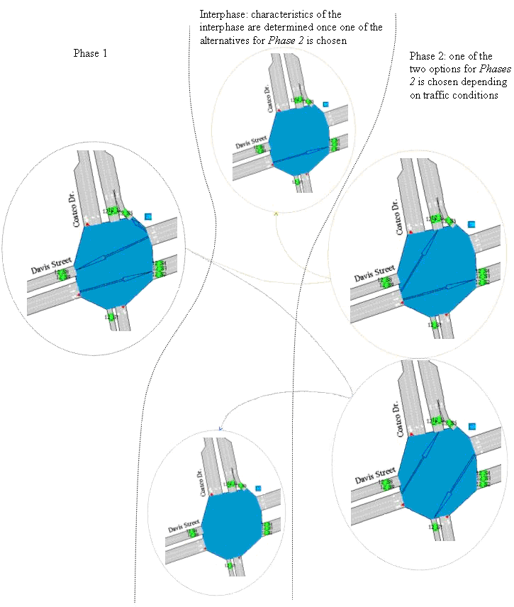
- Interphase: If a phase is defined as an interphase, then this box must be checked. An interphase will always be served at the end of the previous phase and with a fixed duration. An interphase is generally an all-red clearance period.
In actuated controls, however, a turn maneuver might be kept active during an interphase; e.g. in the next illustration the first option in the upper half of the diagram keeps the west-east turn maneuver active during the interphase. If however, the interphase is an all-red clearance period, the actuated system chooses the second option in the lower half.
Only those turn movements that will always be allowed during each phase/interphase should be marked as activated during a phase/interphase. If no explicit choice is made, Aimsun Next will calculate whether a turn movement takes place or not. For instance, in the example of next figure the system will determine whether the west-east turn maneuver is allowed or not during the interphase and it will do so depending on whether phase 1 takes option 1 or option 2. Therefore, when designing the control plan, that interphase is defined with no turn maneuvers.
- Signals: The signal groups belonging to each phase must be checked from the list.