Hybrid Meso–Micro Simulator
Introduction
Traffic modeling is often used to model large complex systems that require different simulation approaches in different areas. The wider area can be modeled with simplified vehicle dynamics while small sub areas require more detailed simulation. Barceló et al (2005)discuss this from a methodological point of view, while Alexiadis (2007) discusses it from a practical point of view.
One example of the need for a hybrid simulation combining a simplified mesoscopic simulation for much of the area with a more detailed microsimulation in critical areas is shown here where the study is focused on the congested central area, but vehicles passing through that area can reroute to avoid it. A full analysis should include the effect of this route choice.
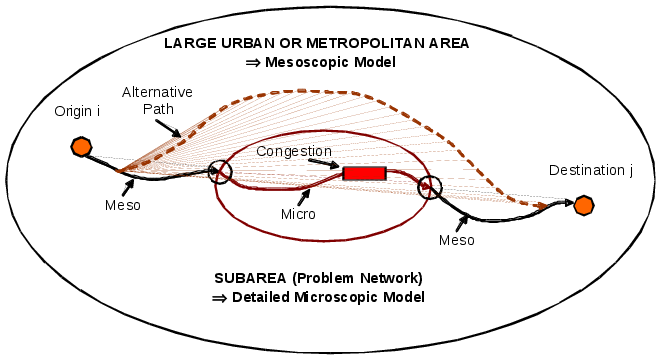
In this example, the central congested are is modeled with microsimulation while the rest of the network is modeled with mesoscopic simulation. A vehicle traveling from Origin i to Destination j is simulated mesoscopically until it arrives at the simulation mode boundary when it is moved into a microsimulation model before resuming the rest of the trip in mesoscopic mode. As the Aimsun Next Mesoscopic model is based on individual vehicles, just as in microsimulation, a particular vehicle trip can be modeled in both modes and moved between modes as required. If the vehicle enters the microsimulated area, it is simulated microscopically, if its route choice avoids that area, then it is simulated in mesoscopic mode for its entire journey.
Crucially, the same network representation and the same flow, speed, and delay information is used in both simulation modes shared in a common database. Route choice decisions for example are therefore consistent between both modes of simulation.
Hybrid Meso–Micro Simulation Process
For a hybrid model to function, the meso model and the micro models must exchange information about vehicles. There are three classes of information:
- Vehicles attributes and statistics
- Vehicle paths
- Network conditions at boundaries.
In Aimsun Next this information is exchanged through two general modules:
- DTA Server The DTA server ensures the consistency of vehicle paths through the network.
- Hybrid Simulator Ensures consistency at the boundaries. There are two different types of boundaries:
- Entrance points represented by centroids: Where vehicles are generated using the specific arrival distribution defined by the user. See the traffic generation process.
- Boundary nodes: In these boundary nodes the vehicles in the upstream sections use different dynamic network models from the downstream sections. For example in the upstream section a vehicle is controlled by a mesoscopic model while in the downstream section the vehicle is controlled by a microscopic model.
The boundary nodes move vehicles from one model to the other model in a similar way to that which vehicles are generated by centroids but in these cases the virtual queues represent modeled road sections rather than the unmodeled areas outside the model boundary.
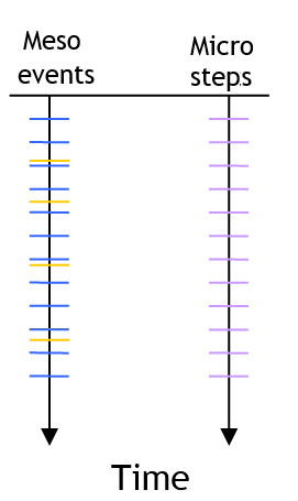
Both models must also be synchronized. As the mesoscopic approach uses an event oriented approach and the microscopic approach uses a time discrete simulation approach, a general clock module is used to generate synchronization events for the mesoscopic model that will update that part of the network The figure below shows the sequence of events in a hybrid simulation The micro side shows the microsimulation time steps. The meso side shows the "normal" mesoscopic events in orange and the synchronization events when vehicles will move in microsimulation in blue.
Modeling Hybrid Meso–Micro Vehicle Movement
Vehicles move through meso and micro areas according to the local models documented in the sections on Microsimulation and Mesoscopic simulation. The important factor in the hybrid simulator is how the boundaries are modeled.
Meso to Micro
To transfer vehicles from the mesoscopic area to the microscopic area, the Aimsun Next Hybrid simulator adopts the same approach that is used to decide if a vehicle can enter the network during a microsimulation.
The following algorithm is used to transfer vehicles from mesoscopic to microscopic areas.
If (IsThereSpace) then
    t = GetArrivalTime
    Schedule a mesoscopic node event from turn at time t
Else
    Schedule a revision for space at time t + SimulationStep
Endif
The process to determine if there is space "IsThereSpace" is explained in the Microsimulation Modeling: Vehicle Entry Section. The function GetArrivalTime applies the microscopic car–following model to get the earliest time a vehicle can enter to the section. Scheduling a node event from turn is explained in the Mesoscopic Node Model Section.
Micro to Meso
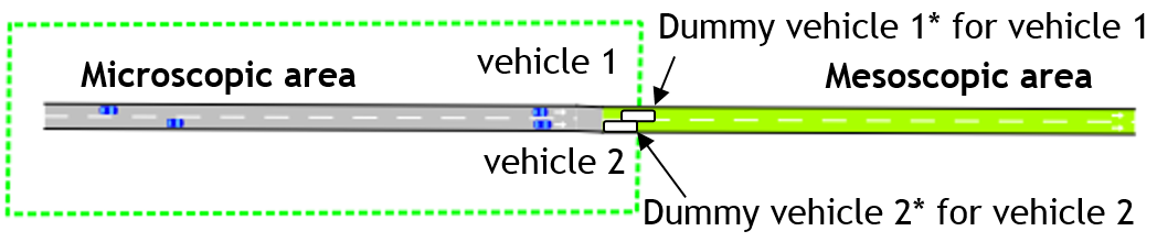
To transfer vehicles from the microscopic area to the mesoscopic area, the Aimsun Next Hybrid simulator uses the time at which a vehicle exits the last microscopic turn as entrance time of the vehicle in the first mesoscopic section. A vehicle in the microscopic area is then given a leader in the mesoscopic area so it is able to apply the normal car-following model and maintain realistic behavior as it approaches the boundary. The hybrid simulator therefore creates dummy vehicles whose speed and position is calculated based on a triangular density–flow fundamental diagram using the procedure described below.
In the example, vehicle 1 in a microscopic area is applying a car-following model with vehicle 1* and vehicle 2 is applying a car-following model with vehicle 2*.
The algorithm to determine the speed and position for the dummy vehicles first evaluates the critical density (K~crit~) where the maximum flow is reached and flow changes from free-flow to congestion. This value is then used to determine if the dummy vehicle's position is calculated from the section and vehicle parameters or if it is assumed that the dummy vehicle has no real effect ( Speed = free flow speed, Position = ∞ )
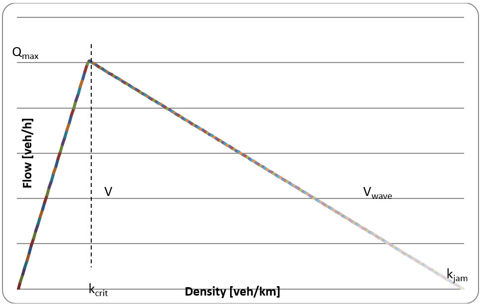
The K~crit~ value is calculated using the following equation:
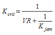
where:
- V is the free flow speed
- R is the vehicle's reaction time
- K~jam~ is the maximum density parameter for the section set in the Section Editor
The algorithm then used to determine the speed and position for the dummy vehicles is the following:
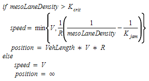
where
- MesoLaneDensity is the current modeled lane density of the section
Microsimulation Areas
Areas which are to be simulated with microsimulation are created with polygons that are converted to Simulation Areas and are activated in the microsimulation scope which is documented in the Hybrid experiment tab
The hybrid behaviors are set in the Experiment Editor: Behavior Tab
The hybrid reaction times are set in the Experiment Editor: Reaction Times Tab