Road Sections
A road section is a group of adjacent lanes where vehicles move in the same direction. The partition of the road network into sections is usually governed by the physical characteristics of the road and the turn movements. For example, in an urban network, a section closely corresponds to the road from one intersection to the next; in a freeway area, a section would be the part of the road between two ramps.
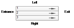
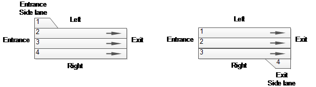
The entrance, exit, right, and left sides of a section are defined according to the direction of movement in the segment. Each lane in the section is identified with a number in the range 1,…,n, from the left to the right of the section, where side lanes are also counted.
Creating a new Section
The section geometry is specified by a collection of points that define straight and curved segments. A section is formed by one or more segments. Each segment can be either a straight segment, defined by the origin and the end points, or a curve segment, defined by an origin point, an end point and either one or two control points. Segments can be used to model the physical shape of the link on the map They are also used to model changes in the road characteristics such as gradient, speed, lane restrictions, etc. which occur in the middle of the section.
To create a section choose the Section tool, click on the view where the section will start, then click again to add a new section point. A double click ends the editing (this last point will be the end of the section). To create a simple, straight section, click once to specify the section start and then double click on the position of the section end.

Geometry specification
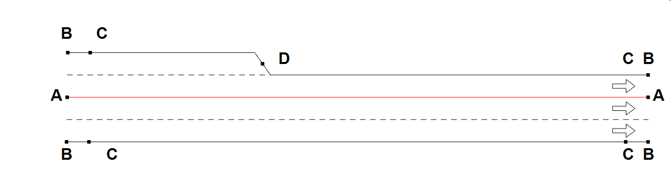
A section can have several straight or curve segments, each defined by a centerline and a number of lanes. The entrance and exit angles to the section can also be modified and side lanes added as required. Section geometry is edited by moving the grab handles associated with each segment to :
- Adjust the end point of the segment (A)
- Adjust the entry or exit angles(B)
- Add a side lane by moving the handle outwards or convert a full lane to a side lane by moving it inwards.(C)
- Adjust the length of the side lane, or remove the side lane, by taking the handle outside the length of the link(D).
- Adjust the width of the section (Line BCCB)
Note that the lane width can be also changed from the context menu, or by using the section editor. See the Section Editor section for more detail.
New curve points can be added using the New Vertex tool for straight or curve segments; see the New Straight Vertex Tool and New Curve Vertex Tool entries in the Line and Polygon Section for more details. An option in the section context menu allows also the creation of vertex in the selected section. If more than one section or turn is selected then the vertex of the target section (the one that shows the menu) will be created on the selected location, in the rest of sections or turns the vertex will be created in the middle. Up to two curve vertices can be created per section, if a third is created, the section is cut into multiple segments.

A section can be cut in two using the Cut tool. If the cut is drawn while pressing the Control key, no node will be created.
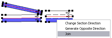
Joining Sections
The Join command, available from the Section context menu, can be used for joining two sections into one or to create a node (and the related turns) to link the selected sections.
Joining Two Sections
Select two close sections (the end of one section must be close to the beginning of another) and select theJoin command. The sections will be joined into one. More precisely, the section from which the command has been executed will be expanded to accommodate the other section, which will then be removed. Only sections that have the same number of lanes at the join point can be joined.
Joining More Than Two Sections
Select the sections that will participate in the node and select the Join command. A node will be created with the corresponding turns.
Main and Side Lanes
Lanes in a section are classified as main lanes or side lanes. In a main lane, vehicles can enter from other sections and exit to other sections: a main lane is both an entrance and exit lane. A side lane can be positioned either on the right or on the left side of the section and is either an entrance or an exit lane.
While a section cannot exist without one or more main lanes, side lanes are optional. A section is not allowed to have more than one side lane per side; an entry and exit lane on the same side is not allowed and the section should be split into two to model this lane layout.
Note: when using Aimsun Next Scripting or Aimsun Next microSDK functions and structures, the lane numbering starts at 0 and is in the range 0,…, n-1
Section Editor
The section editor is used to change the values of different attributes for a single section.
Some of these attributes (such as the name, the road type, the speed, or the capacity) can be more conveniently edited using the section’s context menu. When using the context menu, more than one section can be changed at once.
The attributes of a section can be categorized into:
- Identifier: Name and external ID.
- Generic information: Road type, speed limit, capacity and user defined costs.
- Prohibited Vehicle and Pedestrian Types: Specify restrictions on some agents having access to a part of the network, e.g. bicycles and pedestrians are not allowed on highways.
- Physical characteristics: The altitude of each point and the segment slopes.
- Lane data: Lane width, the type of each lane, detailed segment speeds, solid lines, and shoulder information.
- Dynamic models: Micro, Meso, and Hybrid related data.
- Static model: Macro related data.
- Usage information: What other objects link to this section.
- Virtual queue data: For sections at the edge of the area with congestion that spills back.
The editor also offers information on the section length, taking into account the altitude (or Z coordinate) and the functional class.
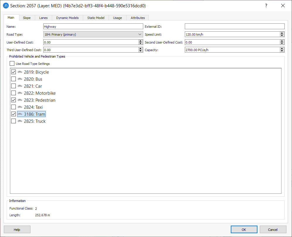
Main Tab
The figure below shows the attributes defined for a section in the Main tab.
Name and External ID
These are internal and external labels for the section. Note that Aimsun Next does not interpret these fields and they can contain any text, or they can be empty. The External ID is useful to store, in Aimsun Next, an identifier, for the same object, from an external database. For example, when a network is created automatically from a GIS database, the External ID will keep the identifier from that database automatically.
Aimsun Next allows discovery, manipulation, and results presentation using the External ID, which simplifies the data interchange.
Road Type, Speed Limit, and Capacity
Sections are classified according to road types specified for the simulation. A road type sets default values for all the section parameters.
Note that changing a value in the road type editor will only change the sections that use the edited road type when the Update Sections button is pressed to propagate the change. See the Road Type section for more information.
The Speed Limit in a section should correspond to the maximum legal speed.
Capacity and Number of Lanes
Capacity
The section capacity can be edited in this dialog. This capacity, however, will be altered automatically if the number of lanes of a section is changed . In this case, the old capacity will be used to calculate the lane capacity (before the change) and the new capacity will be calculated using the lane capacity and the new number of lanes. Side lanes will not be considered when calculating the capacity per lane or the new section capacity.
Examples:
- The number of lanes of a section with two main lanes and a capacity of 2000 veh/h is changed to three. The new capacity will be 3000 veh/h ( 3 * 2000 / 2)
- A section with a main lane and a side lane has a section capacity of 1000 veh/h. The user removes the side lane. The capacity is still 1000 veh/h.
The speed and capacity values are used by the route-choice functions in Aimsun Next Micro and Meso depending on how the attractiveness parameter has been defined. Aimsun Next Macro instead uses capacity or speed for the volume delay functions calculations will use the capacity expressed in PCU's, in its assignment calculations.
User Costs
The three user defined costs are available to contain any data the user might need to store, for example they might be used as a cost expressed in terms of time representing an economic value associated with the section that can be used in a volume delay function (VDF).
For more information about VDFs and other cost functions, see Cost Functions.
Prohibited Vehicle and Pedestrian Types
The prohibited vehicle types and agents are specified here. Also, the list defined at the Road Type level can be used. This specifies the restrictions that some vehicles might have regarding access to parts of the network, e.g. bicycles banned on highways, or goods vehicles banned from urban streets.
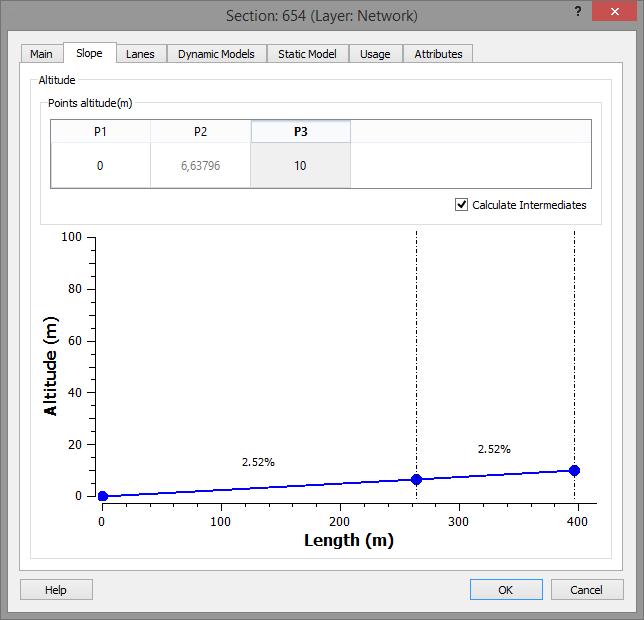
Slope Tab
The editor is used to modify the altitude of the end points of a section by either setting the numerical value or by dragging the point in the altitude graph. If the section is a composite of several joined segments then these intermediate points are shown and their height can be adjusted. Alternately, if the Calculate Intermediates option is checked, then the altitude of these points will be calculated using linear interpolation between the altitudes set for the start and end points.
The altitude of the initial, ending, and intermediate points is also edited using the selection tool. To do so:
- Click on the point to be modified while also pressing the Ctrl key.
- Drag the mouse up to increase the altitude of the selected point,
- Or drag the mouse down to decrease the altitude.
The point that is being modified will show its coordinates but only the Z coordinate will change.
It is also possible to change the altitude of all the section points at once, select the section rather than just a control point. The change in Z co-ordinate will be shown as the mouse is moved. After releasing the mouse, the Z coordinate will be applied to the whole section as an increment.
The influence of the section slope on vehicle movement in a microscopic simulation is detailed in Modeling the influence of the Section Slope in microscopic simulation. Slope units are represented as percentages.
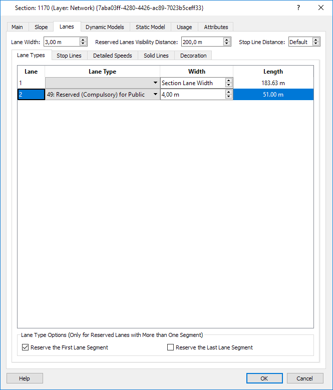
Lanes Tab
This tab allows the editing of lane types (used to reserve a lane for a particular vehicle class), to set speed by lane and/or by segment and to modify the lane width for all the lanes in the section or for individual lanes.
Mesoscopic simulation does not support the use of different speeds for lanes in the same section, it will use the default section value. It is possible to define different speeds at a segment level but taking into account the previous restriction; all lanes have to have the same speed.
Lane Width
The lane width is set for all lanes, but can be overwritten for individual lanes if required. The width does not affect vehicle behavior or interaction between vehicles in adjacent lanes.
Lane Length
The 3D length of each lane is shown in the table.
Reserved Lanes Visibility Distance:
The visibility distance of the reserved lanes that will be used in the target lanes model of the dynamic simulators.
Lane Types and Reserved Lanes
Lane Types are defined in the Lane Type Editor.
Use the combo box to select the reservation type of the lanes, if they are reserved. Alternatively, to reserve a lane for a particular vehicle class; select the section, activate the context menu with the mouse over the lane that will be changed, and choose the Lane Type from the list.
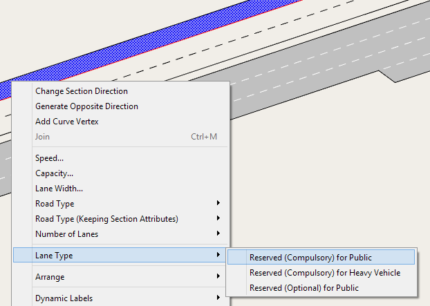
Note that more than one section can be edited at the same time by opening the context menu with more than one section selected to change the lane type for all the lanes selected.
Unreserving the First and/or Last Segment
The first and/or the last segment of a reserved lane can be marked as unreserved, by unchecking the corresponding options; Reserve the First Lane Segment and Reserve the Last Lane Segment. Unreserving the first lane segment is used where the reserved lane is introduced some distance into the section. Unreserving the last lane segment is used where traffic is allowed to enter the lane in the final segment of the section, for example to maintain discharge capacity at a signalized junction.
If the last segment is maintained as a reserved segment, but vehicles can only make a turn by using that lane; then vehicles will start to make their lane change as they enter zone 3 - when the lane change is marked as "urgent"
If the last segment is marked as unreserved and vehicles need to use it to make their turn, then there are 3 possible cases, based on the Aimsun lane changing model
-
The unreserved section is shorter than the zone 2 distance; the unreserved section starts in zone 3: Vehicles will make their lane change decisions at the start of the unreserved section overruling the normal zone based decisions.
-
The unreserved section is between zone 1 and zone 2 distance; the unreserved section starts in zone 2: Vehicles will make their lane change decisions at the start of the unreserved section using the zone 2 rules and moving to the zone 3 rules as they pass the zone 2 distance.
-
The unreserved section is longer than the zone 1 distance; the unreserved section starts in zone 1: Vehicles will make their lane change decisions as normal they reach zones 2 and 3 as if there was no reserved lane.
Note that it is also possible to split the section in two (using the Cut Tool) but it is better to use the reservation options to keep the model as simple as possible (and as close to the physical model as possible).
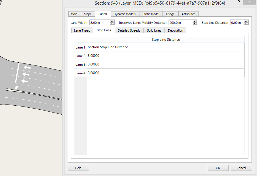
Stop Lines 
Stop lines control where vehicles halt at the end of the section before moving through the node. The default position is at the end of the section but they can be moved individually to modify the junction geometry.
In the Stop Lines subtab, Lanes tab of the section editor, set a stop line offset from the end of the section for each lane individually.
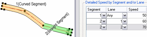
Detailed Speeds
The speed can be set by lane and/or segment. If no speed is specified, the section speed limit will be used by default and the field will appear empty.
Use the Add button to create a new detailed speed. Select the segment(s) and the lane(s) where the speed will be used and enter the new speed limit.
It is possible to select all the segments of a particular lane (put Any in the segment column) or all the lanes of a particular segment (put Any in the lane column). If both the segment and the lane are set to Any, the speed defined will be ignored, as it is equivalent to defining the section speed.
To remove detailed speed information, select it and click the Delete button.
Decoration
This defines the width of a hard shoulder that can be drawn at each side of the section.
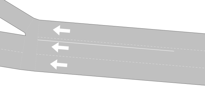
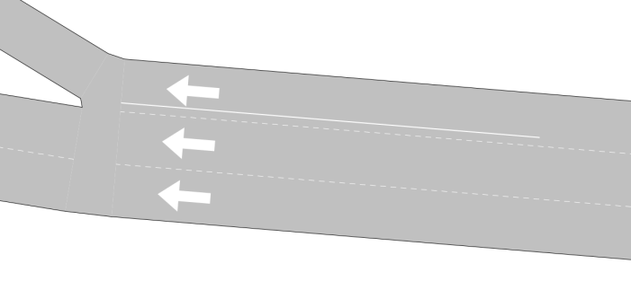
Solid Lines
Solid lines are created on the section using direct manipulation. The steps required for editing a solid line are:
- Activate the Solid Line tool and click on the section lane to the left of the lane separator where the solid line is to be located.
- Using the selection tool select the solid line (the section where the solid line is placed needs to be selected first).
- Drag it to change its start or end points, or move it to the left, right, or center of the lane line.

Solid lines are used in the microscopic simulator to prevent vehicle changing lanes where they are located. They are not considered in the mesoscopic simulator.
Solid lines can be located in three different ways with corresponding different behaviors in vehicles:
- On top of the dotted line that separates two lanes. In this case vehicles will not be allowed to change lanes from left to right neither from right to left.
 - On the left of the dotted line that separates two lanes in the sense of vehicle circulation. In this case vehicles will not be allowed to change lanes from left to right but they will be allowed to change lanes from right to left.
- On the right of the dotted line that separates two lanes in the sense of vehicle circulation. In this case vehicles will not be allowed to change lanes from right to left right but they will be allowed to change lanes from left to right.
Vehicles will not change lane if this implies crossing a solid line (located on its side or on top of the lane separation) during the first half of its lane changing maneuver. If a solid lane separates lanes leading to different turn movements at the end of a section, vehicles that do not manage to reach their target lane before the beginning of the solid line will miss the turn.
Solid lines are propagated across nodes if they are present in the last meter of the origin section and in the first meter of the destination section.
Dynamic models data
The figure below shows the options that appear when the Micro and Meso models are selected and provides the common data used by the vehicle-based simulators.
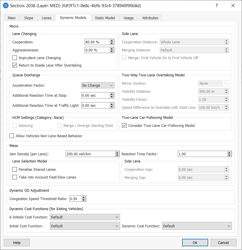
Aimsun Next Microscopic simulator data
Attributes only used in microsimulation can also be set in this editor.
The parameters related to lane-changing are:
-
Cooperation: This parameter denotes the percentage of upstream vehicle cooperation to create a gap for a vehicle trying to change lane.
-
Aggressiveness: This parameter, together with the Aggressiveness Level in the vehicle type, allows vehicles to enter short gaps followed by a relaxation period. The full process respects car following stability. The % of aggressiveness determines which vehicles with aggressiveness will effectively apply it: the percentage of vehicles corresponding to the higher aggressiveness levels. Note that vehicles receiving cooperation do not enter short gaps.
-
Imprudent Lane Changing: This parameter allows vehicles to enter gaps that are too short to respect the car following algorithm stability. The vehicle changing lane, or its follower, will need to brake at a rate up to twice their maximum deceleration.
-
Return to Inside Lane After Overtaking: If this option is checked, vehicles will return to the nearside lane after an overtaking maneuver, Note this is required behavior according to UK and EU driving regulations but is not universally required.
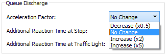
The parameters related to queue-discharge are:
- Acceleration Factor: This parameter locally increases or decreases the maximum acceleration of the vehicles by a factor of 0.5, No Change, 2, or 5.
-
Additional Reaction Time at Stop : This is an additive local correction of the global reaction time at stop. If it is negative, it shortens the reaction time at stop in the section.
-
Additional Reaction Time at Traffic Light: An additive local correction of the global reaction time at a traffic light. If it is negative, it shortens the reaction time to the traffic light change in the section.
The parameters related to side lanes are:
-
Side Lane Cooperation Distance: This parameter is the distance from those side lanes that are considered to be on-ramp lanes. This is used for the specific lane-changing model applied at on-ramps, as described in On-Ramp Model section. This means that a different criterion for determining whether to consider side lanes as on-ramps or not can be applied to different parts of the network. The user can have local control of the on-ramp lane-changing model, making the calibration process easier.
-
Side Lane Merging Distance: This parameter sets the distance from which vehicles are allowed to merge onto the main stream within the On-Ramp model. Setting a larger distance than the Cooperation Distance has no effect. The default value corresponds to 5 times the maximum of the distance traveled in one reaction time and the length of the vehicle, which is chosen to allow the vehicle to merge onto the main carriageway before being required to slow at the end of the ramp.
-
Side Lane Merge: First Vehicle On is First Vehicle Off: Defines whether only the first vehicle inside the On-Ramp model is allowed to merge onto the main stream or if vehicles that are not first in line might also try to merge.
The two-way two-lane overtaking model allows vehicles to overtake each other on a single carriageway road with the overtaking vehicle occupying the opposite side of the road as it passes the slower vehicle. To create a two-way two-lane overtaking area, sections must be linked as Mirrors to each other to allow a vehicle on one to appear to move to the other. To link sections together:
- Edit a two-lane, two-way section by creating a two-lane section,
- Generate the section in the opposite direction (called the mirror section)
- Edit the two-way overtaking model attributes filling in the ID number of the corresponding mirror section. The options in the editor will be either none or the opposite section.
After entering a valid ID number, the mirror section is shifted and resized to be below the original section; both sections can then be graphically edited as a single two-way section. Solid lines can be used to delineate zones in which overtaking is not allowed. These solid lines should be placed in both sections if relevant for both directions.
The Visibility Distance & Visibility Factor: These parameters are discussed in the Microsimulation Modeling; Vehicle movement (Two way overtaking section) along with the corresponding vehicle and network parameters.
The Speed Difference to Overtake with Solid Line is the speed difference over which it is allowed to overtake slow vehicles even with a solid line present.
Vehicles can also be allowed to use the Two-Lane Car-Following Model in this section which includes the influence of the vehicles in adjacent lanes in the car-following model.
Allow Vehicles Non-Lane-Based Behavior activates the non-lane-based model in this section for vehicle types with this behavior enabled.
Note that activating non-lane-based behavior at the section level enables the consideration of lateral clearance in all traffic, that is for both non-lane-based vehicles and lane-based vehicles. For more information, see Non-Lane-Based Microscopic Simulation.
HCM Statistics 
Clicking the Tools/Build HCM Areas option shows the HCM areas in the model. Approaches are represented by a blue polygon, Weaving areas are represented by a dark red polygon and Merge/Diverge areas are represented by a green polygon.
Approaches
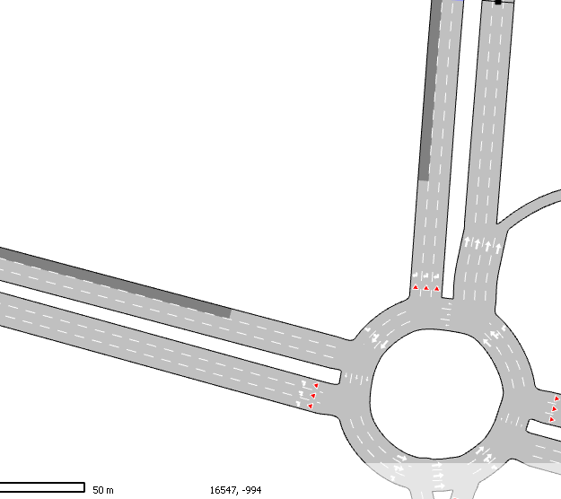
An approach to a signalized intersection is defined, in HCM, to be extended backward from the stop line a sufficient distance to include the maximum queue during the study period, and in any case at least 250ft. Due to geometry configurations, approaches modeled in Aimsun Next can be limited when:
- they reach a signalized intersection upstream
- there are two or more small sections ( as shown below) that share the same upstream sections. In such cases, the approach is split in two having each approach use the sections closer to the intersection.

Weaving Areas
Weaving Areas are where an exit ramp is located after an entry ramp and traffic leaving the carriageway at the next junction has to interact with traffic entering from the previous one as well as the through traffic.

To define a Weaving Area; tick the Weaving option on the section. Normally a weaving area is coded as a single section with two entrance sections and two exit sections.

The option is only enabled when the HCM Road Type section is set to Freeway or Multilane Highway.
Merge/Diverge Area
Selecting Merge / Diverge Starting Point sets the section as either the first section in a merge configuration, which means that it has an entry side lane, or the first section in a diverge configuration, which means that it has an exit side lane. The check notifies Aimsun Next to gather HCM statistics.

The option is only available if the section has an entry or an exit side lane.
Aimsun Next Mesoscopic simulator
The Aimsun Next Mesoscopic simulator model uses the following parameters which are further described in the Mesoscopic Traffic Modeling Section:
- Jam Density: Denotes the capacity of the section. When a lane reaches this Jam Density, the lane is considered to be full and no more vehicles can enter until the first vehicle in the lane leaves.
-
Reaction Time Factor: This is a local parameter that multiplies the global vehicle reaction time. It provides more flexibility in the calibration process by allowing changes the vehicle reaction time in the current section. The model usage of the Reaction Time Factor is detailed in the Mesoscopic Traffic Modeling section. Although in general this parameter will be set to 1, it can be used to calibrate extreme situations; for example:
- Sections with a high slope.
- Sections with a sharp bend to left or to right.
- Other situations liable to be influenced by the vehicle reaction time.
-
Lane Selection Model: There are two options:
- Penalize shared lanes: When a lane is shared by more than one turn-off from the section, it is penalized in the lane selection model.
- Take into account fast/slow lanes: Slow vehicles are biased toward using slow lanes and fast vehicles toward using the fast lanes.
-
Disable Lane Selection in Mesoscopic simulation: Note This option is available in the Attributes tab folder. It disables the lane selection model so all vehicles select the closest lane based on the connectivity of the network. This option should be used only in very specific situations where the internal lane selection model does not fit the requirements of the simulation.
Side Lane: There are two options:
-
Cooperation Gap: It is the amount of time (in seconds) that the mainline vehicles will force to have as headway whenever side-lane (on-ramp) merging vehicles are present. This is to facilitate the incorporation of traffic. The only vehicle that will be delayed is the vehicle on the first mainline lane adjacent to the ramp.
-
Merging Gap: It is the minimum gap that vehicles in the side lane (on-ramp) look for in order to merge into the mainline.
Dynamic OD Adjustment
The congestion speed threshold ratio is used to define if a section is marked as congested as a proportion of the speed limit for a section. It is used in Dynamic OD Adjustment.
Dynamic Cost Functions (for exiting vehicles)
The cost functions used in exiting sections for the dynamic simulator route-choice calculations (see section Note for Aimsun Next Micro and Meso Users) are selected here.
Static Models Data Tab
This tab allows selection of the VDF (volume delay function) to be used by the transport planning operations. It appears when then Static model is selected.
The additional volume is a parameter representing a fixed flow on a section specified in PCUs, which will go through it independently of the rest of the flow on the network. For example, some macro models have used this to model a capacity drop applied to the road network due to bicycle traffic which has been independently estimated.
Usage Tab
This tab displays the usage of this section in other objects such as transit lines, signal groups, or traffic conditions.
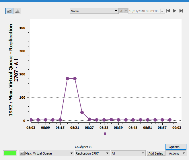
Section Editor: Virtual Queues Tab
If a Road Section is at the edge of the road network, or at the edge of a sub-area, and there is congestion on that segment that causes a Virtual Queue, then a Virtual Queue tab is created for the section. This tab shows the recent history of the size of the queue for different vehicle types.

The complete history of the virtual queue for the simulation period is available from the Time Series Editor as shown below for the same queue.