Non-Lane-Based Microscopic Simulation
Introduction
Aimsun Next's microscopic simulator can model lateral non-lane-based vehicle movements.
The model is intended for city-wide microscopic simulation, so it focuses on large-scale performance and aggregated outputs, rather than the highest fidelity, in representing realistic trajectories for each vehicle.
This permits a more realistic representation of traffic in environments where multiple vehicles can occupy the same longitudinal position within a lane. The ability to activate non-lane-based movements – by vehicle type and section – makes it highly flexible and capable of simulating situations ranging from the specific behavior of motorcycles in lane-based flows (e.g. in European cities such as Barcelona) to fully non-lane-based traffic including vehicle types with a wider range of characteristics (e.g. those observed in Indian traffic).
Activating non-lane-based behavior in the network (at experiment and section level, as explained below) enables the lateral perception of all vehicles present on a section. This makes the widths of vehicles and lanes effective parameters within the simulation.
The sections below provide an overview of the additional parameters required for non-lane-based vehicle movements, the modifications made to the car-following model to include multiple leaders, and the path-selection model used to compute the intended lateral position of the vehicle.
New Model Parameters
The non-lane-based behavior model requires new parameters that constrain the lateral spacing and movements of vehicles. These are named Lateral Clearance and Max Lateral Speed and they can be specified in the Vehicle Type dialog on the Microscopic Model tab > Main subtab.
Handling Multiple Leaders
The non-lane-based approach requires multiple leaders to be considered. The scan for leaders is bound to a rectangular strip, limited laterally by the rightmost and leftmost points the vehicle can reach during its current maneuver, with lateral clearance included and lateral speed considered.
If the vehicle has no lateral movement at that moment, the strip is simply defined by its width plus lateral clearances. If the vehicle is aiming toward some lateral position, the strip extends to the final lateral position, taking the width and lateral clearance into account also.
After the strip is defined, vehicles inside it but whose rear is not entirely visible from the following vehicle's point of view – because there is another vehicle in-between – are discarded, because they only have an indirect influence (they are the leaders of the vehicles that are partially occluding them).
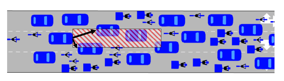
Among all the leaders that fulfill these criteria, the most restrictive one is defined as the one that would be able to halt closest to the vehicle looking for leaders. In the illustration below, two leaders are identified in the downstream strip. The full car-following model is only applied with respect to the most restrictive leader.
Path Selection
Vehicles with activated non-lane-based behavior use a path-selection model to select their lateral position on the road as a full replacement of the lane-based lane-changing and gap-acceptance models.
If a vehicle cannot reach the downstream turn from its current position, or if its current leader is preventing it from reaching a satisfying speed (defined as a percentage of its current maximum desired speed), the vehicle looks for a new path leading to a better position.
The optimal lateral location for each vehicle is computed on the basis of numerous factors, including the valid lanes for downstream turns, current traffic conditions, surrounding vehicles, and vehicle characteristics such as width, lateral clearance, and maximum lateral speed. Many of these characteristics, e.g. the valid lanes, are shared with the Aimsun Next lane-based model, ensuring a seamless integration of the non-lane-based model with all other models.
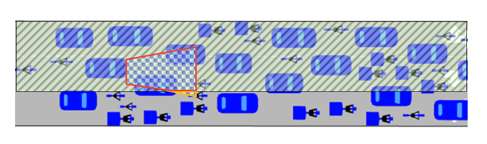
In the following illustration, the hatched area defines valid lanes while the checkered area defines reachable locations within the next simulation step. Maximum lateral speed accounts for the widening of the reachable-locations area. The accessible domain for the best location search, outlined in red, is the intersection between valid lanes and reachable locations.
To avoid lateral oscillations, the decision to look for a better position can be taken every simulation step, as long as the vehicle is not currently heading to a new lateral position, or if the last lateral movement was completed one or more reaction times before.
The forwards visibility in the accessible area is defined by the maximum braking distance of all vehicles in the network. This is the maximum distance from which vehicles in front affect the speed of vehicles behind them.
Visibility is limited to this area to make the model more efficient. The maximum braking distance is defined by the section's speed and the maximum deceleration and reaction times of a vehicle. All vehicle types have the same definition of forwards visibility but it can differ according to the speed of the section.
Activating Non-Lane-Based Behavior in a Micro Simulation
To allow lateral non-lane-based vehicle movements in a micro simulation, the behavior needs to be activated at the following three levels.
- Experiment: specifies which experiments are modeled with non-lane-based movements.
- Vehicle Type: specifies which vehicle types are allowed to make non-lane-based movements.
- Section: specifies which sections in the network are modeled with non-lane-based movements.
These three levels provide flexibility in customizing experiments based on road geometry, location, and traffic composition. For example, non-lane-based movements can be activated only for sections of a specific road type or on approaches to large intersections. The steps for activating at each level are described below.
Activating Non-Lane-Based Behavior at the Experiment Level
In an experiment, click the Behavior tab and tick Allow Vehicles Non-Lane-Based Behavior.
Activating Non-Lane-Based Behavior at the Vehicle Type Level
The non-lane-based behavior option can be activated for all vehicles or for a selected subset of vehicles. For example, in European models non-lane-based movements can be enabled for bicycles and motorbikes while cars, trucks, and buses would retain lane-based movements. In fully non-lane-based traffic, where lateral movements are allowed for all vehicles, the option should be activated individually for each vehicle type.
In a Vehicle Type dialog, click the Microscopic Model tab > Lane-Changing Model subtab and tick Allow Vehicles Non-Lane-Based Behavior. Repeat this for all vehicles you want to model using non-lane-based behavior.
Activating Non-Lane-Based Behavior at the Section Level
The non-lane-based behavior option can be activated for a section, a subset of sections, or for every section in the whole network. You can choose to activate non-lane-based movements only in certain areas of the model where such behavior is observed, e.g. wide streets with highly congested conditions.
To activate non-lane-based behavior in a section, open the Section dialog and click the Dynamic Models tab. In the Micro group box, tick Allow Vehicles Non-Lane-Based Behavior.
Alternatively, use the Table View to set the Allow Non-Lane-Based Movements attribute to True to activate behavior for multiple sections. If not displayed in the Table View, access the attribute by clicking Column Visibility.
Note that activating non-lane-based behavior at the section level enables the consideration of lateral clearance in all traffic, that is for both non-lane-based vehicles and lane-based vehicles.