Aimsun Next Graphical User Interface
Aimsun Next offers a state of the art GUI that includes easy to use editors, direct manipulation of all the graphical elements, unlimited undo and redo, copy and paste within Aimsun Next, copy from and paste to other applications, and print support.
Aimsun Next supports high resolution displays such as Apple Retina displays, scaling icons and images as required. It also supports "Dark Mode" user interface themes available on Windows and macOS. These modes are toggled through the Aimsun Next command line.
The following subsections will describe the main windows in Aimsun Next and the common user interactions.
Application Windows 
The Welcome Window
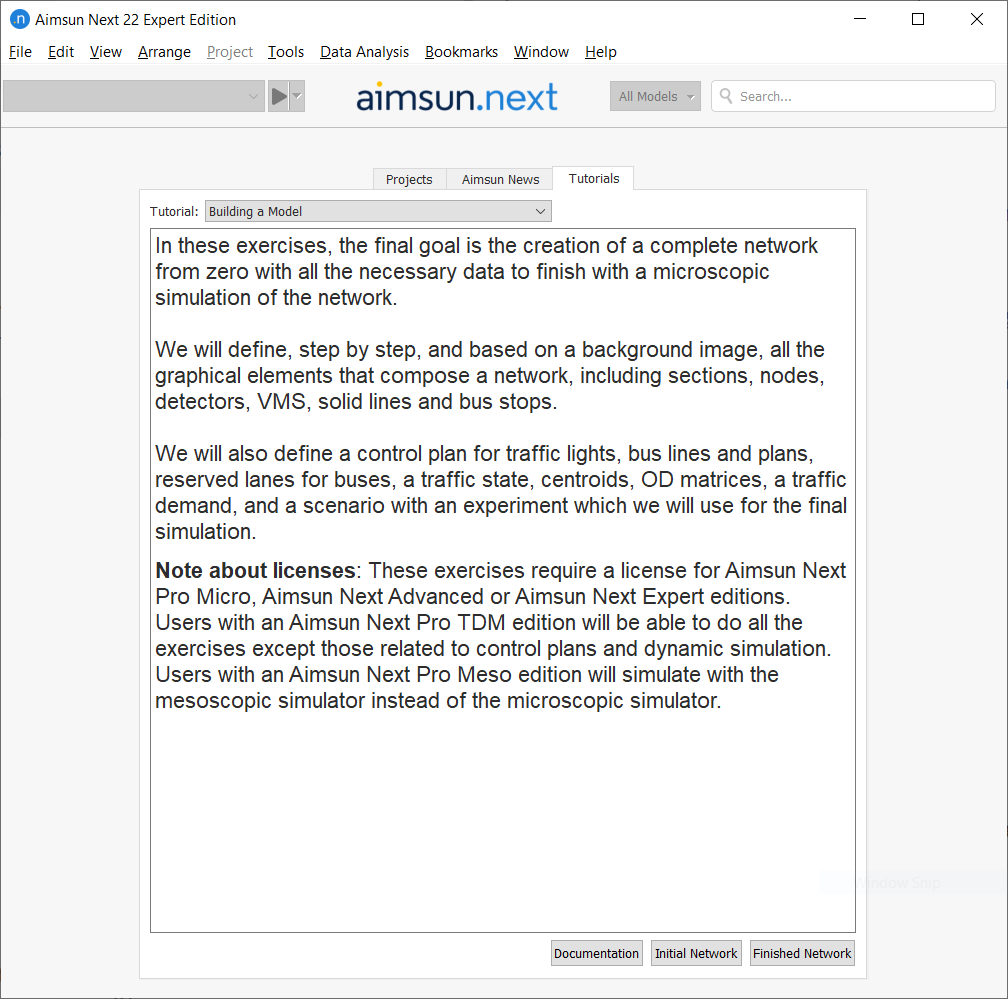
The welcome window appears when Aimsun Next is launched and before a project is selected. It is the first window the user sees as the software starts and it displays the following tabs:
- Projects: A list of the last opened documents. The number of projects displayed can be customized in the Preferences menu. There is also a button to create New Project.
- Aimsun News: A link to the Aimsun News webpage with details of the last software versions released, the upcoming events, and the latest news.
- Tutorials: A diverse set of exercises designed to help the user become familiar with modeling using the Aimsun environment.
The menu bar and application toolbars are covered in detail in the next section.
The Application Window
The main application window includes three basic elements: a menu bar, a tool button area, and a collection of windows (editors, drawing areas, information browser etc.). Any of these elements can be opened and closed individually except for the menu bar which cannot be closed.
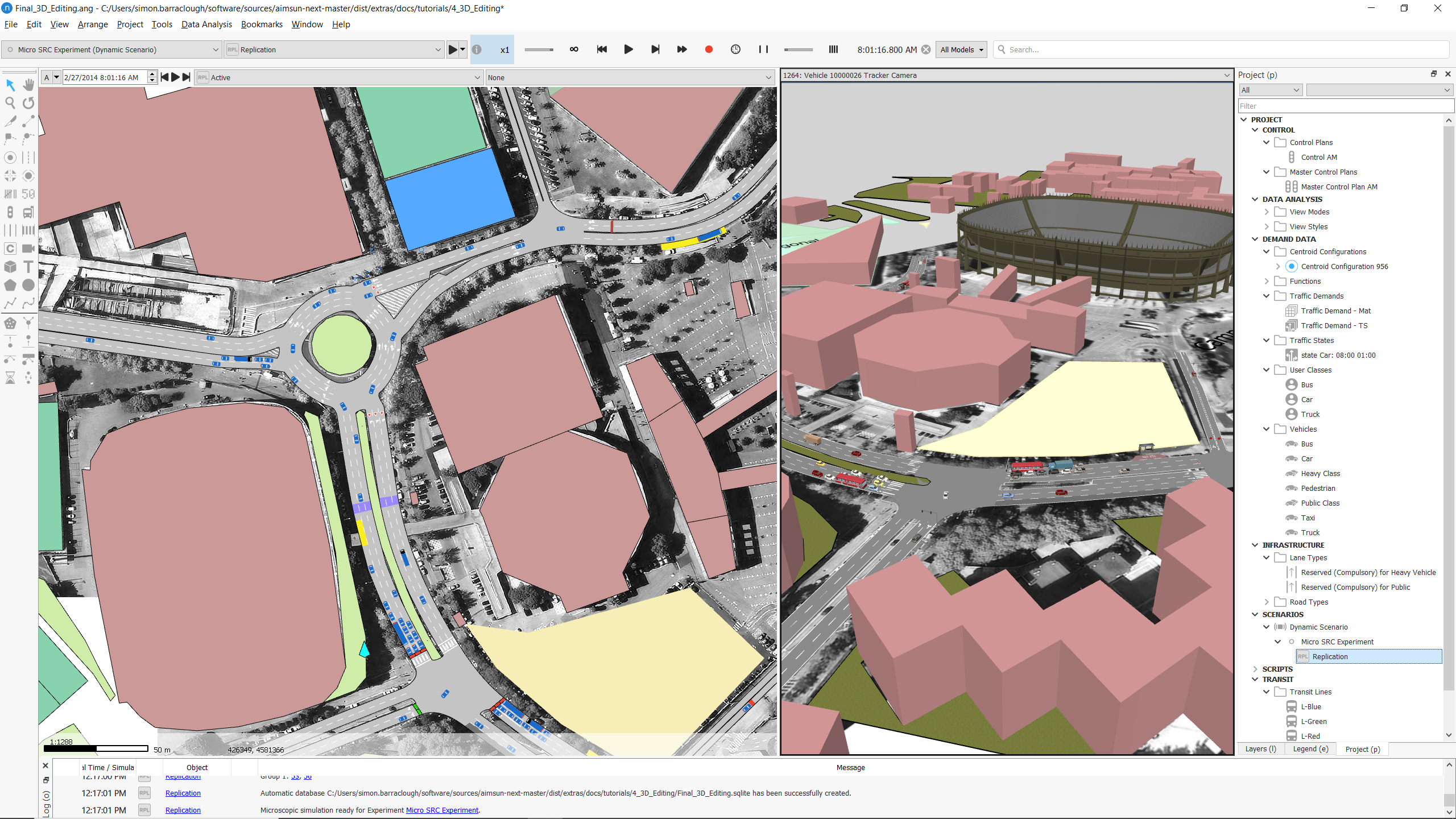
The figure above shows an example of the application window. It contains:
- A menu bar.
- The active experiment and active replication and a task tool bar area (above).
- A 2D view of the network.
- A 3D view of the same network
- The Project Browser showing all the non-graphical objects (Controls, Data Analysis, Demand data ..)
- The Layers Window showing a list of the available graphical layers, which includes the layers derived from any CAD files used in the project.
- A main tool bar area, on the left.
Multi-model
Aimsun Next can open two files at the same time. A separate view is created when two documents are open simultaneously, as shown below:
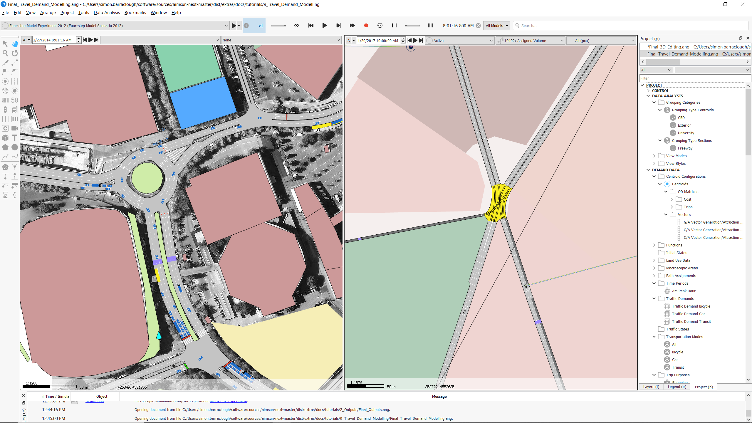
The Project window shows which project is active. To make a project active, select it from the project list in window.
Menu Bar and Tool Bars
Menu Bar
The Menu bar is located in the top part of the application window. It cannot be moved or hidden.
Several functions are accessible in Aimsun Next via the Menu bar, refer to the Quick Reference to Aimsun Next Menu Commands section for an overview of the menu options.
Task tool bar area
Four different boxes are available:
- Experiment and Replication Box: This toolbar contains the main experiment or replication operations such as Scenario Properties, Experiment Properties and running options.

- Task Box: This box displays information about the processes in Aimsun Next. It also contains the play controls of the replication such as the play, pause, restart, step forward, fast forward, record, and stop functions, as well as the information box about the current running model replication. While no task is running, the task box displays the Aimsun logo.


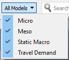
- Models: show or hide parameters for Macro and Travel Demand Modeling, Meso and Microsimulation. Only visible when using the Advanced or Expert Editions of Aimsun Next.
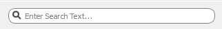
- Find Box: This box provides a search function to find any graphical or non-graphical element in the project. The results from a search can be refined to search for object by attribute, i.e from the list of road sections with speed < 50 km/h. Refer to the Find Dialogfor details.
2D View Toolbars 
In Aimsun Next, the 2D view forms the primary graphical area where the network is drawn. Multiple 2D windows can be created, each showing a different view of the network; each view has two toolbars and a status bar.
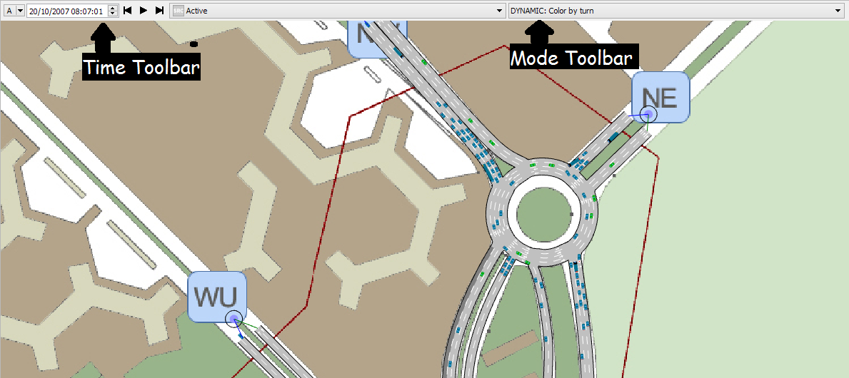
The two toolbars are the Time Toolbar and the Mode Toolbar.
- Time toolbar:
-
The date and time of the 2D View can be defined.If the drawing mode is based on a Time Series The Play button will start an animation drawing the elements depending on the values in every predefined number of seconds and during a predefined interval. The dialog that opens when selecting the Set Time option in the View Menu is used to define the parameters for the animation.
-
Mode Toolbar:
- The view Drawing Mode used to draw the graphical network elements in the view.
Context Menus
Aimsun Next uses the right mouse button to access to a context menu for the object currently under the mouse. This menu displays a list of operations that can be performed on the selected item. Any object that can be selected will show a context menu.
The menu displayed will depend on the current selection, for example the context menu of a section is different from the context menu of a node. When a context sensitive menu option is selected, Aimsun Next will apply this command to all the selected objects, not only to the object that the menu shows. This allows us, for example, to change the speed of more than one section at the same time. If any of the objects of a multiple selection do not accept the command (for example, the section option Change Direction cannot be applied to a node), then no change will take place on this object.
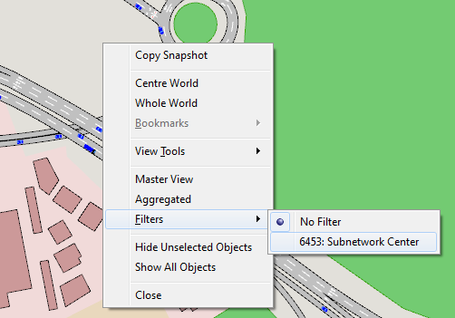
The View window context menu is also used to:
- Set that view as a Master View: All the zoom and pan actions applied to this view will be also applied to all the other open 2D Views keeping the same center point for all the views. Refer Pan and Zoom section for details.
- A filter to be applied to the drawing elements can also be chosen. There will be a filter for the whole network and another one for each Subnetwork
View Navigation
In 2D views, the pan and the zoom tools are used to move around and change the drawing scale of a view  . Alternatively, the middle mouse button and the scroll wheel can be used to move around the view.
The View menu includes commands to change the view scale (the zoom factor) and the position in 2D views:
- Whole World: Displays all the network elements in the view.
- Whole World Filtered: Displays all the network elements in the current subnetwork (if any).
- Center World: Move the view such that the center of the network in the center of the view; the zoom factor is not changed.
- Maximum Zoom for Visible Car Detail: Sets the 2D view to the widest that can still show vehicles.
- Pan To: Pans to a user supplied position, in absolute or lat/lon coordinates.
- Pan To Object Being Edited: Pans the object being edited where it has a physical position, i.e. the mid point of a Transit line, subnetwork, section, node, centroid etc.. This option has no effect if the object has no position i.e. transit plan, scenario etc.
- Show Latitude & Longitude: Toggle the co-ordinate display from the default co-ordinates to Latitude & Longitude.
- Show Object tooltips: Shows a tooltip with the ID of the object under the mouse pointer.
In 3D views, the same pan and zoom tools are used, as well as the camera rotation tool to move around the view. Refer to the 3D views section.
Finally, Bookmarks provide navigation to predetermined positions in the view.
The Mouse
In 2D views the mouse button actions are:
- Left button click: Performs an operation depending on the selected tool (selection, rotation, object creation…).
- Middle button click and drag: Pans the view.
- Wheel button: Zoom in or zoom out (depending of the wheel movement).
- Right button click: Brings up the relevant context menu.
In 3D views, the mouse button actions are:
- Left button click: While the selection tool is active, clicking onto an object will select it in both 2D and 3D views, and clicking onto a vehicle will create a new camera placed inside the vehicle to follow its movement.
- Middle button click and drag: To move up, down, left or right (depending on the mouse movement done while the button is pressed).
- Wheel button: To move the camera forward or backwards.
- Right button click: Brings up the context menu with two functions, to take a snapshot of the view or to close the view.
Pan Tool
To use the Pan tool to move around a 2D view. Select the tool, press on the view and, without releasing the mouse, move the pointer to navigate in the view.

The Pan tool is also available using the middle mouse button when another tool is being used. This allows navigation around the window, even when another tool is selected and in use (for example, during the section creation, it is possible to move the view).
Another option to move around the network is made available when the Pan or the Zoom tools are selected. When any of these tools is active, the arrow keys and the extended keyboard number keys with the Num Lock deactivated will produce the corresponding views:
- ‘Up’ key: moves up half the window height
- ‘Down’ key: moves down half the window height
- ‘Left’ key: moves left half the window width
- ‘Right’ key: moves right half the window width
- ‘5’ key: centers the view
- ‘Page up’ key: zooms in
- ‘Page down’ key: zooms out
- ‘Insert’ key: shows the whole view.
When any of the four arrow keys is pressed while pressing theCtrl key, the view is moved by one window width or height.
Zoom Tool
The Zoom tool is used to change the 2D view scale. This tool is also available using the wheel mouse. A click will zoom in, pressing the Shift key while clicking will zoom out.

The view scale determines not only how close the objects will appear but also which objects are visible (using the layer visibility setting).
When two 2D views are available, using the Zoom to select an area while pressing the Alt key in one view will make the other view show this area.
Editing Objects
There are three main types tools used in editing objects:
- Selection tools: Used to select objects.
- Modifier tools: Used to change some attributes of graphical objects using direct manipulation.
- Editing tools: Used to add, copy and remove new graphical objects.
Some tools (creators and connection) will become inactivate automatically after a single use. This means that for creating, for example, two centroids, the centroid tool is selected to create the first centroid and selected again to create another one.
The continuous mode for a tool will keep the designated tool active until it is explicitly deactivated (activating another tool). This mode is activated by selecting the tool with a double click instead of a single click.
Note that when the continuous mode of a tool is activated, no other action other than the tool action can be performed.
Selection Tools
Use this tool to select objects, to open the editor for an object and to manipulate the graphical elements.

A click on an object will select it and any other selected object will be deselected. If click is on the background, the previously selected objects will be deselected.
If the Shift button is pressed during a selection, the process will be modified as follows:
- If the object is not selected, it will be selected and the rest of the selected objects will remain selected.
- If the object was selected it will be unselected, keeping the rest of the selected objects selected.
Another option is to select all the objects inside an area. Click on the drawing area and, without releasing the button, move the mouse to define a selection rectangle. Release the mouse button to select all the objects placed totally inside this rectangle.
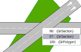
When more than one object lies at the same point, if the Alt key is pressed while the left mouse button is clicked, then a list with all the objects laying at that point will appear to be able to select the desired one. For example, in the example shown below, two sections and a polygon are located where the mouse has been clicked, the menu allows the correct one to be selected.
Other Selection options
It is also possible to select objects using mechanisms as:
- Select all the found objects in the Find Dialog.
- Select all the objects inside a layer Layers Editor.
- Select all the objects in the current network using the Select All command in the Edit menu.
- Inverse Selection in the Edit menu that will deselect the current selected objects and it will select the ones that were not selected.
Objects can be selected, individually or in groups by selecting an area or using the Shift key while clicking on additional objects. Any graphical operations such as rotation, translation, raising or lowering are then applied to all the objects.
A double click on an object will make its editor appear or if the object is already being edited the editor will be brought to front. When an editor has the focus, Pressing F11 will make it progressively more translucent and more opaque as the F12 key is pressed.
Other, more specific, operations can be applied to objects of the same type using the context menu (for example setting all the selected nodes as Yellow Box). Note that commands invoked from the context menu will be applied when possible to all the selected objects and not just to the object that showed the context menu.
Modification Tools
Object Editor
A double click on an object will open its editor. Editor dialogs always show the OK and Cancel buttons to confirm or abandon the changes; pressing the ESC key in an editor dialog is equivalent to pressing the Cancel button.
If an object is completely behind one of its dynamic labels, pressing the Alt key while double-clicking will open the object editor and not the dynamic label editor.
Even when more than one object is selected, only one editor will be opened, the corresponding to the target object (the object that receives the double click). The commands in the context menu, however, will be applied to all the relevant selected objects.
It is not possible to Undo changes performed by an editor dialog.
Translation
The selection tool can also be used to translate all the selected objects to a new position. Click on a selected object and, without releasing the button, move the mouse to translate the current selection to a new position. Release the button to end the translation operation.
Altitude
The altitude of each object is changed pressing the Ctrl key as the left mouse button is pressed. Mouse movement now changes the Z coordinate of the selection instead of its X and Y coordinates.
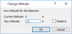
Alternately the Change Altitude option in the Arrange menu, or the (Arrange / Change Altitude) option in the graphical object's context menu can be used to bring up the Altitude dialog. The new Altitude can be entered here; if the Relative option is checked, then the height is relative to the current altitude.
To change the altitude of one or more points of a section, polyline or polygon; select just the points to be changed rather than the whole object and adjust the altitude as described above.
Shape
The shape attributes of a selected object can also be edited using the selection tool. Click on one of the shape handles and drag it to a new position to edit the shape of an object. Objects such as sections have context specific shape editing, for example, changing the length of a section, its lane width or to adding a new side lane (on-ramp or off-ramps). Refer to the relevant section in this manual for specific edit options for each type of object.
Rename
Selected objects can be renamed pressing the Rename key (F2 key by default). This is also true for non graphical objects such as control plans or traffic demands.
Show ID
To show an object identifier for an object or group of objects in a 2D view, the Show Label command in the context menu can be used. The labels can be hidden with the Hide Label option.
Rotation
This tool allows the rotation around the center of all the selected objects.

The rotation center is initially set to the center of the current selection and is indicated by a cross. This can be moved using the mouse. The rotation tool is used as a selection tool to select or unselect elements using the click and shift + click operations.
Editing Tools
Undo and Redo
Any operation done using direct manipulation can be undone and redone. Both operations are accessible from the Edit menu, from the Edit operations toolbar or using the standard shortcuts Ctrl+Z for undo and Ctrl+Y for redo.
If the changes are accepted in editor (pressing either the OK button or the Enter key) the current undo/redo list of commands will be discarded. That means that no undo will be possible for commands applied before the modification made by using the editor.
There is no limit to the number of commands that can be stored in the undo list except for the physical limit imposed by the available amount of memory in the computer.
Copy and Paste
Aimsun Next allows graphical elements to be copied (such as sections or centroids) as well as non-graphical elements (such as OD matrices or vehicle types). The copy operation can be done using the Copy, or Cut, and Paste commands (from the Edit menu, from the Edit operations toolbar or using the standard shortcuts Ctrl+C for Copy, Ctrl+X for cut and Ctrl+V for paste) or via drag and drop.
Pressing Shift+Alt+C will copy the object ID only. It can then be pasted into documents or scripts that require just the ID.
Graphical Objects
For graphical objects, the whole selection will be copied or cut at once. When copying the selection, the selected objects will not be affected. When cutting the selection, the selected objects will be removed after placing a copy in the clipboard. After copying or cutting objects, they can be pasted in a 2D view, either in the current network or in another network edited in a different instance of Aimsun Next. After a paste operation, pasted objects will be selected. Any other selected object will be unselected.
Paste Context
The paste operation needs a context, a place to put the data that comes from the clipboard. This context will be a view (in the case of graphical objects) or another object (for non-graphical objects) which becomes the new owner of the pasted data. The paste operation must be consistent with normal project organization rules, for example, if an experiment is copied then the paste must be executed on a scenario (as all the experiments must belong to a scenario), it would be impossible to paste it to a replication (a replication cannot contain an experiment). The context where the paste operation will take place is the object that has been selected by the user when the user executes the Paste command, either from the Edit menu, from the Edit operations toolbar or using the Ctrl+V shortcut.
Drag and Drop
The Project browser supports drag and drop for copy/paste operations. In a drag and drop operation the user selects the data to be copied (an OD matrix for example) and, without releasing the mouse’s button, drags the data to drop it afterwards, releasing the button while the mouse pointer is over the object where the dragged data is to be copied.
Group/Ungroup
Often it is convenient to group objects together to be copied and pasted within the 2D view. By selecting several objects, then selecting Group from the Arrange menu on the menu bar or in the context menu, simple items (e.g. 2D shapes) can be combined into more complex items to be copied elsewhere within the view.
Copy Snapshot
This operation (accessible from the Edit menu or the View context menu) will take a snapshot of the current 2D view and will place it as an image in the clipboard. This image can be pasted afterwards in other applications (as an image editor or a text processor).
Marks in Editors
When an object is edited and it affects or uses other objects, these objects will be drawn in the active 2D view using the marker colors. If more than one object is to be marked and they play different roles, then different marker colors will be used as follows:
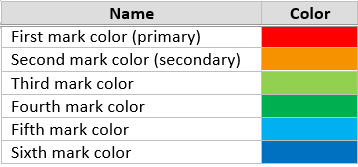
These colors are defined in the mark.xml color ramp and, like any color ramp used in Aimsun Next, it can be customized.
Examples of the mark color usage are:
- The transit line will show the sections that are part of the route using the primary mark color.
- While assigning turns to a Signal Group the turns that are already part of the signal are drawn using the primary mark color. The turn selected is drawn using the secondary mark color.
In general, the editor will try to offer as much context information as possible to ease the editing process.
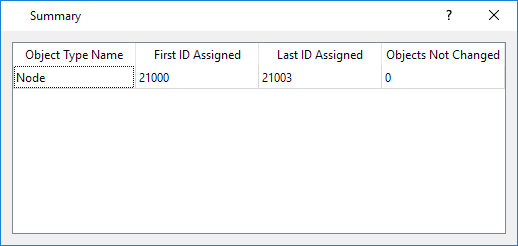
External IDs 
The external IDs of object are used to reference them in scripts or in post-simulation data processing. External IDs are not set by default but are created by the user as objects are edited.
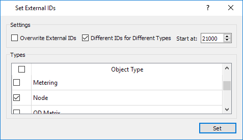
The External ID tool assigns an external ID to every object in the simulation or to objects of a specified type to automate the process of assigning IDs. Setting IDs in different ranges to different object types is advised to ease subsequent identification of objects by type or ID.
There are options preserves, or overwrite existing external IDs and to ensure that IDs are unique for all objects rather than unique amongst objects of the same type.
The figures below show an example of assigning External IDs to those nodes that do not yet have IDs assigned - preserving the existing External IDs and assigning IDs in the range from 21000 to those nodes. The summary shows that IDs 21000 - 21004 were assigned, while 10 nodes were left unchanged.
Keyboard Shortcuts
The main tools can be activated from the keyboard pressing the following keys:
Key Sequence Tool ---------------- ------------------ F2 Rename Tool
F5 Selection Tool
F6 Pan Tool
F7 Zoom Tool
CTRL + R Rotation Tool
F9 Connection Tool
The main windows can be activated from the keyboard pressing the following keys:
Key Sequence Window
P Project Window
L Layers Window
E Legend Window
O Log Window
T Table View Window
S Transit Segments Window
In order to control the execution of the active experiments if they are micro or hybrid meso-micro:
Key Sequence Action
F3 Run Animated Simulation (Autorun)
SHIFT + F3 Run Animated Simulation
F4 1 Step in the current Animated Simulation
SHIFT + F4 Pause/Continue the current Animated Simulation
Other shortcuts that can be used in the UI are:
Key Sequence Action
CTRL + C Copy selection
CTRL + V Paste (previously copied selection)
CTRL + SHIFT+ V Paste at original location (previously copied selection)
CTRL + G Group selection
CTRL + U Ungroup selection
CTRL + [number] Set the number of lanes of the current selected section, if any. Otherwise, new sections created will have the specified number of lanes when creating them.
CTRL + M In Windows and Linux: Join sections. In Mac: minimize application.
SHIFT + ALT + C Copy IDs
F11 Toggle simple view
CTRL + F11 Full screen
CTRL + Q Menu file -> Quit
CTRL + P Print
Inside the script editor the following keys can be used:
Key Sequence Action
CTRL + N Indent line
CTRL + U Unindent line
CTRL + E Execute script