Managing Traffic
Aimsun Next vehicle-based simulators include support for traffic management operations to modify the traffic network conditions, to affect driver behavior, or to simulate events on the traffic network.
A traffic management strategy consists of a number of policies which are applied to a traffic network to solve a problem or achieve a goal, for example to reduce congestion at a peak hour or to manage traffic around roadworks. Each policy has an action or can have a number of complementary actions, for example a lane closure can be matched with a corresponding permission for private vehicles to use a transit lane, or an incident resulting in a lane closure, modeled on one side of a dual carriageway can be matched with a speed reduction on the other side of the dual carriageway to simulate the "rubber necking" behavior of curious drivers.
Strategies are intended to solve Problems where these Problems are owned by one or more Transport Authorities. In Aimsun Next, a strategy can contain multiple Policies where each policy can be owned by a different Authority. The simulation is therefore providing tools to include the administration of traffic management strategies in the model as well as the implementation of these strategies.
Note: Traffic management strategies can only be applied to dynamic simulations (Microscopic, Mesoscopic and hybrid Micro-Meso). See the available Traffic Conditions and Policies per simulation engine.
Authorities and Problems
Authorities
An Authority is the body responsible for approving a policy. A strategy can have several policies, with each policy the responsibility of a different Authority. In order to apply a complete strategy, all the Authorities must agree. This is typically true on large scale networks, for instance, networks which span administration or geographic boundaries.
The simulator allows experimentation with variations on this agreement. A strategy is activated at the scenario level, but the policies contained in that strategy are activated at the experiment level. Therefore, it is possible to set up an experiment to test what happens if all the Authorities agree or if only some of them give permission; Authorities are therefore used in two ways:
- Owner Authority: The one that manages (that wants to apply) the strategy. This is applicable in the Strategy editor.
- Operating Authority: The one that must authorize the changes to be applied on the network. This is used in the Policy editor.
Authorities fulfil an informative function only, although scripts can be used to automate which policies are implemented if only some, but not all, of the Authorities can act as the strategy is applied.
Authorities are created from the Project Window Traffic Management context menu and have no other properties than their name and external ID and any attributes assigned through scripts.
Problems
Problems are created from Project Window Traffic Management context menu. They identify an owner and contain a description of a traffic management issue for which strategies to solve it will be tested in the traffic model.Problems just supply information about a strategy and do not contribute to the simulation.
Edit the Problem description in the text field, available in the Problem Editor.

Strategies, Policies, and Traffic Conditions
A Strategy is a holder for a collection of policies which will applied in whole or in part to the solution of the Problem. A Policy is a component of a Strategy and there might several co-ordinated policies to implement a single strategy. Policies contain actions which can be changes to the traffic network or to the management of the network. Policies can be implemented through multiple complementary actions, i.e. co-ordinated lane use changes and speed restrictions.
A Traffic Condition is similar to a policy in that it is a collection of actions that are applied based on a set of triggers.
The difference between a traffic condition and a strategy with a set of policies is that traffic conditions are used to represent current changes on the network that are not part of any traffic management action. There is no management choice if they are applied or not because they represent events that occur in a network. Traffic conditions in effect simulate unplanned events on the network.
For example, a speed reduction can be used by an operator to increase the capacity of a highway during a peak hour. This change will be modeled as an action within a policy as it is planned and controlled. However a speed reduction can also be due to accidents. Here the limitation is present in the network, but was unplanned and not due to actions of the road network managers. In this case, a traffic condition should be used.
Traffic conditions also add a new type of action appropriate to a temporary unplanned event: this action closes a small length of lanes within a section.
Strategies
Strategies are created from the Project Window Traffic Management context menu as shown below.

Strategies can depend on an Owner Authority and be used for a Problem. This information is supplied in the Strategy Editor with a description about the Strategy. More information about Authorities and Problems is given in the Authorities section and in the Problems section.

Policies
A Policy is a collection of actions that are activated together at the same time.
Actions have just a single effect and are the building blocks used to reproduce a situation on the network or specify a driver action. Sometimes a situation must be coded using more than one action. Policies are created from the Strategies context menu.
Policies are activated on certain conditions, time or triggers. When a policy is activated, all the actions it defines are applied. When a policy is deactivated, all the actions related to it are deactivated too. The activation and deactivation of a policy can be done based on four possible conditions:
- Always: The policy is activated at the beginning of the simulation or at the beginning of the warm-up (if the apply on warm-up option is activated) and is never deactivated.
- Time: The policy is activated at a given moment (the From parameter) and deactivated after some time (the Duration parameter).
- Trigger: The policy is activated when a condition on the network takes place (when a trigger evaluates to true) and deactivated when a second condition happens to take place (another trigger evaluates to true). The parameters are the trigger the policy will be Started By and the trigger it will be Stopped By.
- External: The policy is triggered by a script.
An Operating Authority can be specified for each policy.

Traffic Conditions
Traffic conditions are very similar to policies: they are a collection of actions that are applied based on a given condition. This condition can be, as is the case with a policy, applied always, during a time interval or based on an internal or external trigger.
A traffic condition is created using the Project / Traffic Management / New / Traffic Condition menu option.
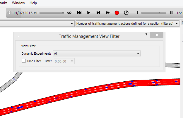
View and Find Active Actions
To see where traffic management actions have been programmed, select the Mark Traffic Management Locations in the context menu of the Experiment. This will generate a new View Mode which will mark those objects that have actions associated with them.
Similarly if a section has actions attached to it, these will be listed in the section usage tab in the Section Editor.
When an action begins or ends; a message is generated in the Log window.

Actions
Traffic Conditions and Policies can deploy one or several actions. The available actions are:
| Action | Usage in SRC | Usage in DUE | Usage in Meso | Usage in Micro | Usage in Hybrid Macro–Meso |
|---|---|---|---|---|---|
| Lane Closure | Yes | Yes | Yes | Yes | Yes |
| Turn Closure | Yes | Only influences path costs | Yes | Yes | Yes* |
| Turn Cooperation Model Activation | Yes | Yes | No | Yes | No |
| Speed Reduction | Yes | Yes | Yes | Yes | Yes* |
| Forced Turn | Yes | No | Yes | Yes | Yes |
| Force Path Update | Yes | No | Yes | Yes | Yes |
| Destination Change | Yes | No | Yes | Yes | Yes |
| Park and Ride | Yes | No | Yes | Yes | No |
| Section Incident | Yes | Yes | Simplified | Yes | Yes* |
| Periodic Section Incident | Yes | Yes | Simplified | Yes | Yes* |
| Deactivation of a Reserved Lane | Yes | Yes | Yes | Yes | No* |
| Control Plan Change | Yes | Yes | Yes | Yes | Yes |
| Section Behavioral Parameters Change | Yes | Yes | Yes | Yes | No |
| Turn Behavioral Parameters Change | Yes | Yes | Yes | Yes | No |
| Transit Route Change | Yes | Yes | No | No | No |
Some actions have a compliance level where:
- When compliance level = 100, then this is a compulsory action
- When 0 < compliance level < 100, then this represents the probability that a specific vehicle will follow the action
- When compliance level = 0, then vehicles follow the action according to the guidance acceptance level parameter for the Vehicle Type.
In many actions, a section is required and can be selected from drop down list of sections. Alternately, clicking on a section in the main 2D view while the action editor is open will select that section.
In actions where vehicles are rerouted either due to section closures, turn closures, or a destination changes, their path will be marked as "TRJ" in the Path Analysis Tool.
Actions marked Yes* in the Hybrid Macro–Meso column have some limitations when used in the macro area of the hybrid macro–meso model. These limitations are explained in each action described below.
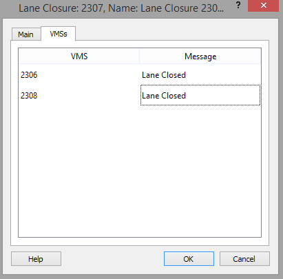
VMS tab
Each action has a VMS tab attached to its editor. Aimsun Next does not require a VMS to activate an action in the simulation, but in reality the action has to be communicated to drivers and often this is done via a VMS. Therefore an action in the simulation can activate a message in one or more VMSs. This is done for presentation reasons, to demonstrate in 3D visualization that a sign has been activated, it does not affect the simulation.
The VMS tab presents a list of all VMS signs, the message associated with this action is supplied here for each sign.
Lane Closure
This action closes a lane in a section. Its parameters, shown in the next figure, are the section, the lane, the range of segments of the section that must be closed, and the class of vehicle for which it will be closed. The visibility distance of the lane closure to be used in the valid target lanes model is also specified. This controls when vehicles start to adjust their lane use to take into account the impending closure.
In hybrid macro–meso simulations, the macro area applies a simplified version of the lane-closure action. In this version, the action is applied to the whole lane and does not take into account the visibility distance because lanes are not distinguishable at the macro level. Additionally, the action cannot be applied to specific vehicle types because it changes the network costs, which apply to all vehicle types equally.

Turn Closure
This action closes a turn movement. It can only be used when the demand is defined using OD Matrices. The turn closure can affect the whole turn or only a subset of its lanes. When closing the whole turn, the options are:
- The origin and destination sections of the turn.
- The origin and destination centroids of the vehicles that will be affected by the turn closure.
- The Vehicle Class that will consider the turn as closed.
- The compliance level of the closure.
If required, the turn closure can be restricted to specific lanes. This will then be applied to all vehicles in the simulation with no filtering by OD centroid or vehicle class. For hybrid macro–meso simulations, this option is not available if the action is applied inside the macro area.

In both cases, the visibility distance of the lane closure to be used in the valid target-lanes model is also specified. The Visibility Distance parameter is used to specify the location where vehicles will change their path or change the set of valid lanes to be used.
In the screenshot below, the selected turn closure with a Visibility Distance of 200 m can be applied in any of the sections highlighted in green. As the closure occurs, a vehicle within the visibility distance will update its path to avoid the closing turn. For hybrid macro–meso simulations, inside the macro area, the turn closure visibility distance can be shortened when crossing a macro–meso boundary or encountering an entrance section. Both cases are notified in the Log window.

In an SRC simulation, when a vehicle encounters a closed turn, it will compute a new path to its destination; this is true for all vehicles regardless of the type of path they are using. If the Influence Path Costs option is selected, then the closure is taken into account when the paths are recalculated. The turn is therefore removed from the shortest path tree calculation, and new SRC paths computed while the closure in effect will not include it. Hence, vehicles entering the network after the closure, and after the paths recalculation, will not be able to select paths that include that turn.
In a DUE simulation, vehicles do not change path in mid-trip and therefore will not find a new path to their destination if they encounter a closed turn. Hence, any Close Turn actions used in a DUE simulation without the Influence Path Costs option activated are ignored and vehicles will continue to use their original path. If a Close Turn action is used with the Influence Path Costs option selected then paths will be recomputed and used by newly generated vehicles but those already in the simulation will continue on their original paths. Paths derived from a DUE which includes a Close Turn action should therefore be checked to ensure that are compatible for use in a subsequent one-shot simulation with the same Close Turn action.
Turn Cooperation Model Activation
This action modifies the priorities of selected turns. The cooperation model can be activated on a turn and vehicle-type basis. When applied, vehicles with priority at the turn will cooperate with the selected vehicle type, whereas under normal circumstances these selected vehicles would be required to yield. This action is not available in the macro area of a hybrid macro–meso simulation.
The amount of cooperation depends on the % cooperation of the destination section of the priority turn. This is set in the Section Editor. A cooperation of 100% will trigger a zipper behavior in congested situations. A cooperation of 0% leads to behavior dictated by a pure yield model.

This action is only applied in microscopic simulations.
Speed Reduction
This action changes the speed of a section, all the sections belonging to a specific road type or a turn. Groupings can also be used to apply the speed reduction to several objects. When changing the speed of a single section, the lane and segment affected can be specified. When changing the speed of a grouping of sections or all the sections belonging to a specific road type the new speed will affect all lanes and segments in the sections. The type of object to be changed is selected in the Object Type drop down list. If the type is Section then the lane and range of section segments can be specified.
The maximum speed of a vehicle in a section or turn is calculated as the minimum of the vehicle's maximum desired speed and the section/turn speed limit multiplied by the vehicle's speed limit acceptance. The new speed specified can override just the section speed limit or the section speed limit multiplied by the speed limit acceptance. When the speed reduction action is intended to ignore the speed limit acceptance, choose the second option.
If a Vehicle Class is specified, only vehicles belonging to this class will be affected by the speed reduction when they enter the section segment containing the change.
In mesoscopic simulation, it is not possible to change the speed for a subset of lanes. This action can only change the speed for all lanes. Changing the speed for a specific segment of a section is possible in a mesoscopic simulation, taking into account that internal mesoscopic segments' length might be different due to model implementation details.
In a hybrid macro–meso simulation, when applied to a macro section or turns, it also affects the speed of all lanes. It is also applied to all vehicles types.

Forced Turn
This action forces a turn on a vehicle depending on its origin and/or destination (if OD matrices are used) or on its desired turn (for both OD matrices and traffic states).
Note: This action is not activated in DUE simulations.
The Forced Turn editor can specify whether this action will be used in a scenario with traffic demand composed of OD matrices or traffic states. For the macro area of hybrid macro–meso simulations, the action is only available for scenarios with OD matrices.
If traffic states are used, only the from and to sections are required to determine the desired turn. Vehicles planning to take this turn will be forced to change. If the OD Matrices option is used, the centroid configuration and the origin and destination centroids can also be specified, as well as an optional section in the downstream path. This forces vehicles on a trip whose planned path will subsequently include that section to take the forced turn.
The section where the forced turn starts can be selected with a left-click. The section in the downstream path can be selected with CTRL + left-click. Alternatively, these sections can be selected from a drop-down list. The visibility distance specifies the point at which vehicles will change their path or change the set of valid lanes to be used at the turn. In this way they take the new forced turn into account.
For the macro area of hybrid macro–meso simulations, the visibility distance is not considered because lanes are not distinguishable at the macro level.
The forced turn can be to one or more destination sections and the proportion of vehicles going to each destination section is specified. The original turn can also be included in this list, in effect only diverting a proportion of vehicles. If the origin section and the newly specified destination section are included in a subpath, then a list of subpaths which contain that turn is given and the proportion of vehicles taking that turn that will then take that subpath can be specified.
The vehicle class filter specifies which vehicles will be affected by this action. You can also provide the desired compliance level.


Force Path Update 
When simulating using OD Matrices, this action causes vehicles to select an alternate route to reach their destination from the current section.
Candidate vehicles for forcing path assignment update are selected by the trip they are on, specified by a centroid configuration and origin and destination centroids. In the example here, vehicles from any origin which are on this section going to the designated destination are candidates for path assignment update. A subset (here 75% of all classes) is selected in the vehicle filter.
Note that this action is not activated in DUE simulations.
The new route can either be the shortest route, or a route selected via one of various Discrete Choice Models (Binomial, C-Logit, Logit, Proportional). Selecting one of these options causes a context specific set of parameter settings to be requested in the editor. If the option to Re-Evaluate when Travel Time is Updated is selected, then vehicles on the section where the action takes place, that will have already assessed their next turn after the action was enacted, will reassess their route choice when a normal DTA route choice recalculation occurs. Hence they will take into account any change in their optimum path and change their path decisions accordingly.
The section where the forced path update starts is selected with a left click, the section in the downstream path is selected with a CTRL left click. Alternately, they can be selected from a drop down list of sections.

Destination Change
When simulating using OD matrices, this action changes the destination centroid of a vehicle.
Note that this action is not activated in DUE simulations.
The section where the action takes place and the centroid configuration must be specified, along with the OD pairs affected and the new destinations for these OD pairs. The new destination can be a new centroid or a list of centroids with different probabilities that must total 100%. The filter specifies which vehicles on the section will be affected by this action by vehicle class considered and the level of compliance.

Park and Ride
When a simulation uses OD matrices, this action changes the destination centroid of certain vehicles, sending them to an alternative park and ride centroid where their trip ends (the second part of the trip to the final destination being a transit trip).
In the Park and Ride editor, the section and centroid configuration must be specified, along with the affected OD pairs and a set of new destinations for these OD pairs. The filter specifies which section and which vehicle class will be affected by the action. A Percentage of Compliance can also be specified.
This action is not available for the macro area of a hybrid macro–meso simulation.
The park and ride action requires:
- All destination and park and ride centroids must be connected to a set of transit stops.
- An alternative destination centroid (the park and ride site) is a candidate only if it is connected with transit lines to the final destination centroid.
- The Scenario must have a Transit Plan and statistics for transit (Scenario/Outputs to Generate) must be active to calculate the expected arrival time of each transit vehicle at each stop.

The action evaluates:
- Expected Cost: The total path cost of the vehicle to reach its destination and assigned as the disutility of the final destination.
- Expected Cost using Transit: For each alternative park and ride centroid, this is the minimum travel time for taking transit and reaching the final destination.
Then, if the alternative centroid has a park and ride cost function, the disutility of this alternative is found by evaluating the function. Otherwise, the disutility is simply the expected cost using transit.
Finally, a Logit function is applied with a configurable Scale Factor to determine the percentage of vehicles diverted to each one of the park and ride sites and to the final destination without using a park and ride.
Note that this action is not activated in DUE simulations.

Section Incident
This action blocks a chosen area on the selected lanes, thus producing an incident in a section (this represents, for example, a stopped vehicle blocking part of a section). The parameters for this action are:
- The section where the incident will occur.
- The visibility distance of the incident to be used in the valid target lanes model.
- If a speed reduction is to be applied to the incident to slow vehicles as they pass it. If the reduction is to be applied, the distance upstream and downstream of the incident is specified, as well as the target reduced speed. The defaults are 200m each side and 50 km/h.
Note: The speed reduction does not apply to mesoscopic models or hybrid macro–meso models. In the macro area, the visibility distance is not applied because there are no lanes.
The remaining parameters shown in the editor, the location and size of the incident, are edited in the 2D view by moving the incident object to its place in the section using the handles on the incident rectangle to vary its length and lane use. In the editor, these values are shown but are not editable.

Periodic Section Incident
This action creates random incidents inside a specified area according to the combination of an interval and a duration. During the time interval specified, it will create single or multi-lane incidents following the time patterns defined in the Periodic Section Incident dialog.
For example, this action can generate an incident that happens every 3 minutes and which blocks traffic for 1 minute in lane 2 along a specified length of a chosen section. One of many uses for this type of incident is to model the effects of changing on-street parking. Setting up periodic incidents is covered in Exercise 6 of the Managing Traffic tutorial.
The data to be defined in the Periodic Section Incident is separated into two groups: Where and What. The parameters in Where specify the rectangular area inside which periodic incidents will occur. The parameters in What specify what kind of incidents will occur.

Where
- Section: Select a section in which periodic incidents will occur.
- From Lane and To Lane: Select the range of lanes in which incidents will occur.
- From Position: Input the start point of the area inside which incidents will occur.
- Length: Input the length of the area (you can also drag and position this area manually in the 2D view).
- Visibility Distance: Input the visibility distance of each incident to be considered in the valid target-lanes model.
What
- Incident Length and Deviation: Specify the length of the periodic incidents. Add a deviation value to this length is required.
- Lanes to Cover: Select the number of lanes to be affected by incidents.
- Starts Every and Deviation: Input an interval for the creation of each incident (one every 3 minutes, or 5 minutes, etc.). Add a deviation value if required.
- Duration: Input the length of each incident. Add a deviation value if required.
Differences between Micro and Meso/Hybrid Simulations
In microscopic simulations, the incidents are placed randomly within the specified area. The size, frequency, and duration of incidents are implemented according to the set parameters in the Periodic Section Incident dialog.
In mesoscopic and hybrid macro–meso simulations, the frequency and duration of the incidents are implemented but the size of incidents is ignored and instead incidents cover the whole incident area, which is considered as a homogeneous block. All lanes in the area will be blocked when incidents are generated. In these cases the following parameters are ignored: Incident Length, Lanes to Cover, and their Deviations. See also Mesoscopic Traffic Incidents.
Reserved Lane Deactivation
This action removes the restrictions on a previously defined reserved lane, making it accessible to all vehicles. This action is not available in the macro area of a hybrid macro–meso simulation. The parameters to define are:
- The section where the reserved lane should be deactivated.
- Which specific reserved lane/s in the section will be deactivated.
- The range of segments to deactivate.

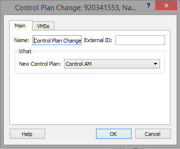
Control Plan Change
This action changes the default control plan defined in the scenario to the one set in the action editor.
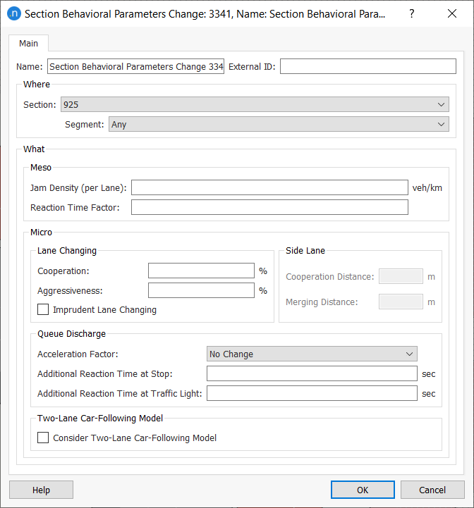
Section Behavioral Parameters Change
This action changes several microscopic and mesoscopic parameters of the section:
- Mesoscopic:
- Reaction Time Factor in a specific section - overrides the default values.
- Microscopic:
- Reserved Lanes Visibility Distance.
- Lane Changing parameters.
- Side Lane Changing parameters. This action will only be available in sections with a side lane.
- Queue Discharge parameters.
- Two-Lane Car-Following Model activation.
This action is not available in the macro area of a hybrid macro–meso simulation.
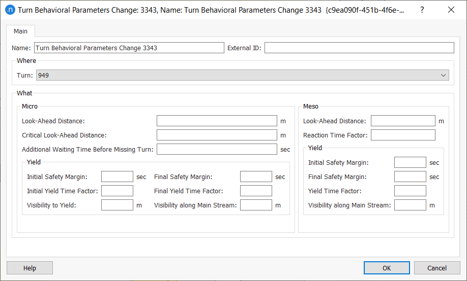
Turn Behavioral Parameters Change
This action changes several microscopic and mesoscopic parameters of the turn:
- Microscopic:
- Look-Ahead Distances. These changes are only available when the turn starts from a subset of lanes of the origin section.
- Additional Waiting Time Before Missing Turn parameter.
- Yield parameters. These changes are only available when the turn has a Yield or Stop sign.
- Mesoscopic:
- Look-Ahead Distance. This change is only available when the turn starts from a subset of lanes of the origin section.
- Turn Reaction Time Factor.
- Yield parameters. These changes are only available when the turn has a Yield or Stop sign.
This action is not available in the macro area of a hybrid macro–meso simulation.
Transit Route Change
This action enables you to reroute transit (public transport) lines as part of a strategy to mitigate or avoid congestion or other network problems. You can specify and edit the desired detours. Currently this action is only available in micro and meso simulations; hybrid macro–meso and hybrid meso-micro simulations are excluded.
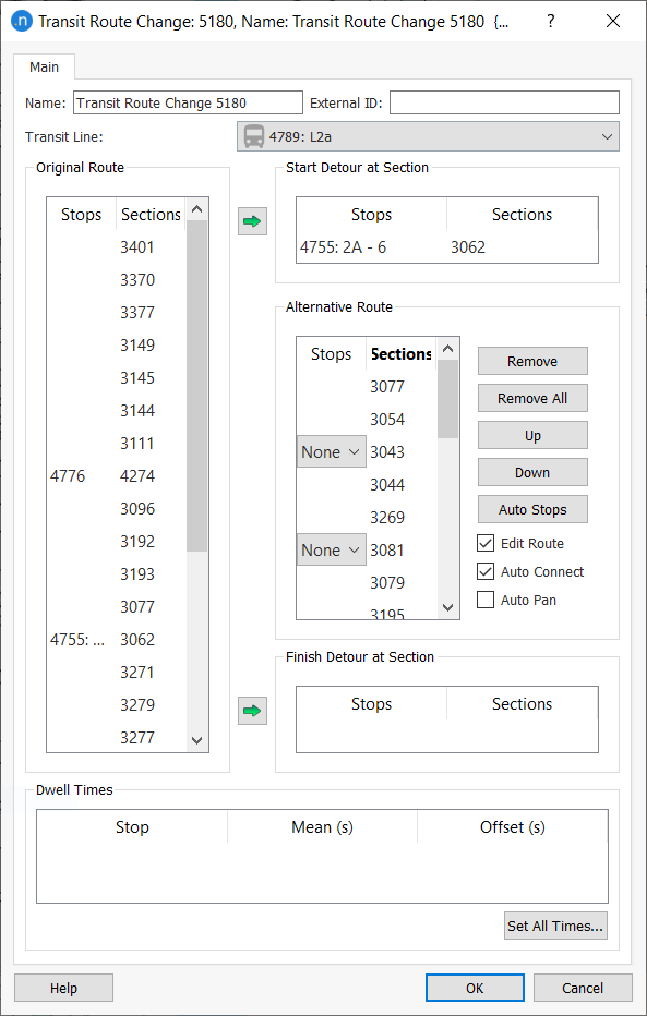
The parameters to define are:
- Transit Line: Select the affected line.
- Start Detour at Section: Select a section or transit stop from the Original Route list and click the green arrow to specify where the detour starts.
- Finish Detour at Section: Select a section or transit stop from the Original Route list and click the green arrow to specify where the detour finishes.
- Alternative Route
- Click on viable sections in the 2D view to specify the route of the detour. These are added to the Alternative Route box.
- Organize the elements of the detour by clicking Remove, Remove All, Up, Down, or Auto Stops as required. Auto Stops adds all viable transit stops to the new route.
- Edit Route: Tick to make the detour editable.
- Auto Connect: Tick to automatically connect viable sections using the shortest physical path between them.
- Auto Pan: Tick to pan the 2D view to the route of the detour.
- Dwell Times: Input Mean and Offset values for all transit stops in the detour.
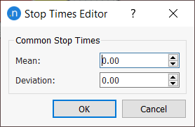
-
Set All Times: Click this button to open the Stop Times Editor where you can set the same Mean and Deviation values for all viable transit stops in the detour.
When you click OK to close the dialog, you will be notified of any errors in the detour and you can continue to edit the route.
Transit Route Change and Geometry Configurations
If your project uses geometry configurations that interrupt or break transit lines in the base (or 'control') network, you can use transit route changes to repair the lines.
In this way, you can run experiments with alternative geometry configurations in which detours are used by the software to reconnect breakages to transit lines. See Using Transit Route Change Actions with Geometry Configurations for more information.
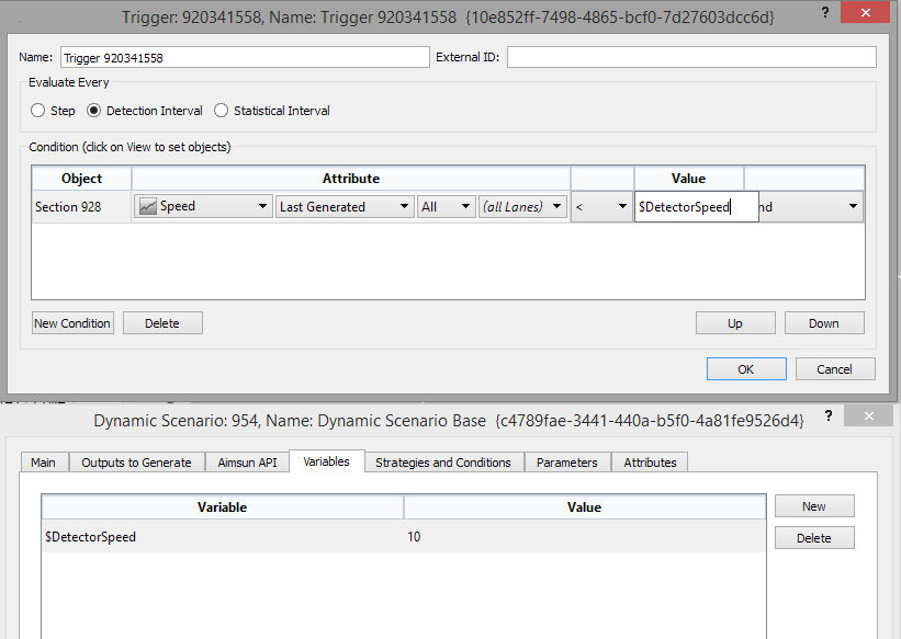
Triggers
A trigger is an expression than evaluates to true or false. The expression is a collection of conditions based on the current state of a selection of network elements (sections and detectors).
Triggers are created from the Project / New / Trigger menu. The expression to be evaluated is defined in its editor. The next figure shows an example:

The trigger can use values of attributes of detectors and sections. Among the attributes that can be used from detectors are:
- Count
- Density
- Headway
- Occupancy
- Speed
- Presence
The attributes for sections include:
- Density
- Delay Time
- Flow
- Maximum Queue Length
- Mean Queue Length
- Speed
- Stops (Number of stops)
- Travel Time
- SI Virtual Queue (Only available using the microscopic simulation )
- SI Density (Only available using the microscopic simulation)
These attributes are evaluated every time that statistics are collected (for sections) or at the detection interval (for detectors, when the data is aggregated) during a simulation. Only attributes beginning with SI (Simulation Instantaneous) are available every simulation step. The interval of evaluation is defined in the Evaluate Every box.
While SI attributes are available, it is recommended that triggers are based on Last Generated Time Series values as in the real world, this is the data available for traffic control systems. Similarly, measures such as the number of stops are not directly measurable on the physical road and are in effect a proxy for a more abstract measure of congestion. It is therefore recommended that triggers are detector conditions, based on Last Generated values, and are evaluated every detection interval. Consideration must be given to either how the measure might be implemented in reality to simulate a practical control system or to how the measure reflects driver's responses to their own perception of traffic conditions.
To create a new condition, select New Condition and click on a section or a detector in the main 2D Window. Select the attribute, the operation (Equal, Not equal, Greater than, Less than ...) a value and a link operation to the next condition. Ordering of conditions can be changed by moving them up or down the list.
Triggers are not evaluated during a DUE simulation. The use of triggers to activate and deactivate actions is not available in hybrid macro–meso simulations for actions applied inside the macro area.
Trigger Evaluation
The different conditions in a trigger are always evaluated from top to bottom so, for example, the evaluation of:
- A or B and C would be: (A or B) and C
- A and B or C would be : (A and B) or C
- A or B and C or D would be ((A or B) and C) or D.
Complex conditions such as (A or B) and (C or D) are not currently supported.
Variables
Instead of using numeric values to be compared with the value of the attributes, variables can be used to provide these values. These values will be set at the scenario or the experiment level, see, for example, the Experiment Editor. This would allow a policy to be triggered when the speed of a section is below 20 Km/h in one experiment and below 10 Km/h in another, while using the same policies and triggers in both experiments.
If variables are defined in a scenario or experiment, the value field is no longer limited to numeric values and variable names can be entered.