Centroids
Centroids are the origin and/or destination of trips in a transportation network when using OD matrices. They can be connected to Sections, Nodes, Transit Stops and Transit Stations.
A centroid connection is used to introduce flow in the network (a Generates to connection), in which case it is drawn in blue, or to extract flow from the network (an Attracts from connection) in which case it is drawn in green. It is also used to introduce passengers in the Transit network, for Transit Assignment. In this case, bidirectional connections for transit stops and transit stations are used, drawn in purple.
A centroid can be connected to more than one object. This means that the centroid will introduce and/or extract flow/passengers from more than one section, node or stop. How the flow is assigned to each connection is set in the Centroid Editor.
Each centroid belongs to a centroid configuration to help manage the demand in the traffic network.
Graphical Editing
Use the Centroid Tool to create new centroids. Select the tool and click in a 2D view to mark the position of the new centroid.

A centroid can be moved, renamed, and duplicated (using Copy and Paste commands) although changing a centroid's position will not change its links to nodes, sections, and stops, and hence not change how the flow enters or leaves the network.
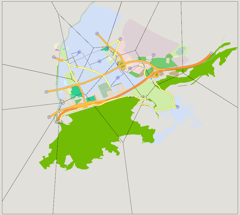
A centroid represents a zone, a geographic area in the network, where travel demand originates and terminates. For graphical visualization it can be linked to a polygon to represent that area. This is created using the centroid context menu.
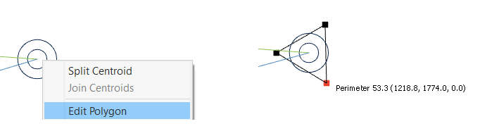
The shape of the Polygon can be edited, or the menu option Tools:Centroid Tessellator can be used to automatically partition the network.
Centroid Editor
Double-click on the centroid to bring up the edit dialog.
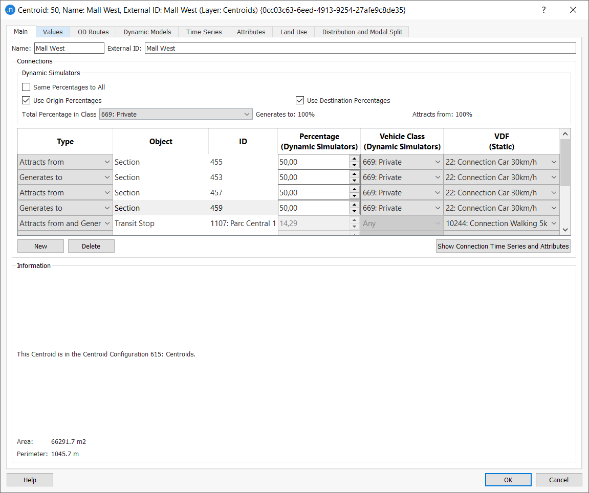
Main Tab
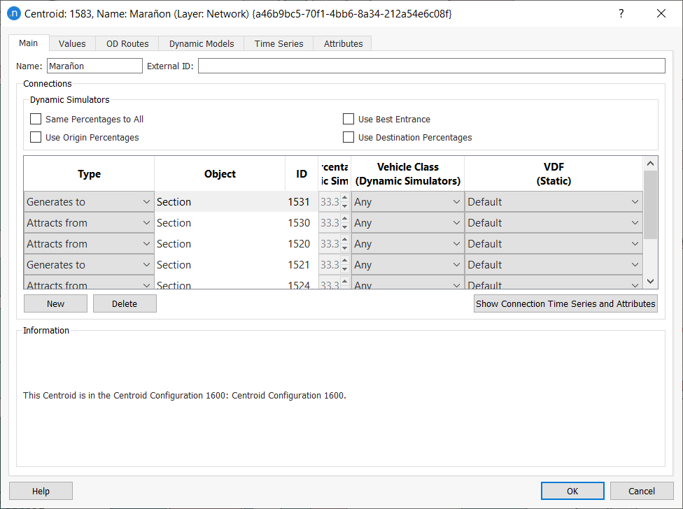
The main tab edits the name and external ID and links the centroid with the objects it is connected to. When a centroid is connected to more than one object to insert or attract traffic flow, it is possible to determine how these different connections will be used in Dynamic Simulators.
When set in Same Percentages to All, the usage percentage will be evenly shared by all the connections - no editing of the percentage is allowed. Otherwise, the usage percentage for each connection is set individually and must total 100% (But see the note about the use of Geometry Configurations below).
When the Use Destination Percentages or Use Origin Percentages option is set, the flow is split according to the proportions specified in the main tab. A section or node can be linked more than once to the centroid if the usage is to be set differently for different vehicle classes. If these options are not set, the link is made to the section with the lowest route cost as calculated by the Route Choice model.
The Use Best Entrance parameter sets whether the route choice algorithm will take into account, for each origin centroid and for each calculation, only the one shortest path from the entrance with the lowest cost (Use Best Entrance checked) or one shortest path from each entrance section (Use Best Entrance not checked).
With any of the connections selected in the table clicking the Show Connection Attributes button will change the editor view to the data for that connection.
Press the Show All Connections button to return to the original view.
Connection Editing
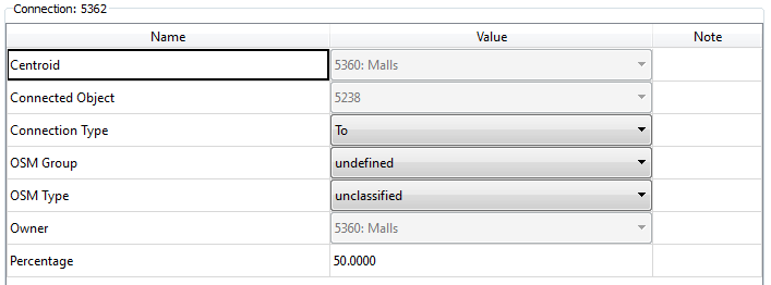
Press the New button, then press on the section, node, transit stop or transit station that will be connected to the centroid. A connection has the following attributes:
- Type: To define if the vehicles will be generated to the object or attracted from the object where this centroid is connected to. The third option, bidirectional connections Attracts from and Generates to are only to be used for transit stops and transit stations.
- Percentage (Dynamic simulators): Whenever the Use Origin Percentages or Use Destination Percentages options are ticked, this parameter defines the percentage of vehicles to use this connection.
- Vehicle Class (Dynamic simulators): A centroid connection can be used by specific vehicle types only. If that is the case, a vehicle class with the allowed vehicle types must be defined and selected here.
- VDF Macro: The Volume Delay Function that corresponds to this connection. If no function is specified, the Default functions are used.
Connections can also be created outside the editor using the Connection tool. Refer to the Connection Tool section for details.
Note for Geometry Configurations
If a centroid is connected to one or more sections which are not present in all the Geometry Configurations listed in the Aimsun document, then the percentage split might not add up to 100% for each and every combination of Geometry Configurations. There are several options to cope with this situation:
- Allow Aimsun Next to set the percentage split for all sections and do not set splits manually.
- If a centroid is connected to sections 1,2,3 in one configuration and 1,2,4 in another, ensure the splits for 1 and 2 are the same .
- Edit the connecting sections to ensure there is a single common section connecting to the centroid for all Geometry Configurations.
- Duplicate the centroid and edit the demand and the splits in different matrices for each copy of the centroid. Create new Traffic Demands to hold the edited matrices and select a Traffic Demand for the scenario that is consistent with the Geometry Configuration.
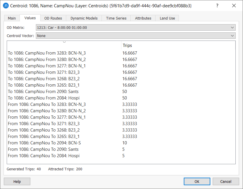
Values tab
In the Values tab, the information about the number of OD pair values,defined in each matrix and linked to this centroid is shown.
When an information line is clicked, the other centroid in the OD pair is marked in the primary color in the active 2D view. The total generation and attraction capacity of the centroid for every matrix is also shown.
OD Routes Tab
In the OD Routes tab, all the routes that start or end at this centroid are shown.
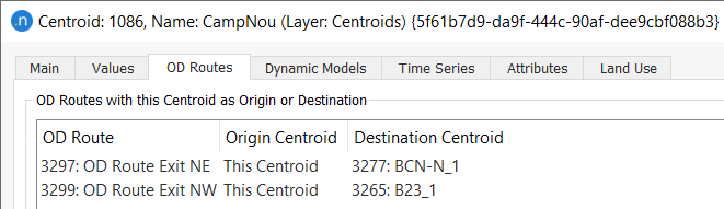
When selecting a route, it is drawn in the 2D views using the primary color.
See the OD Route Editing section for details on editing OD Routes.
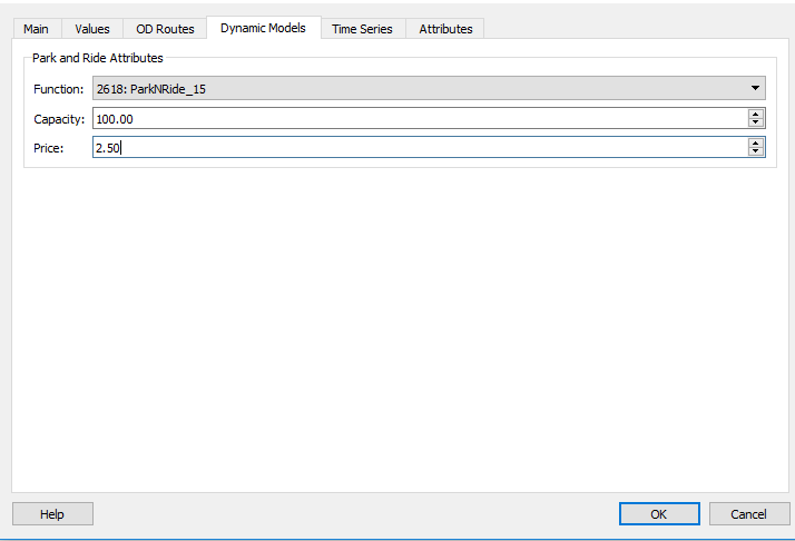
Dynamic Models Tab 
The Dynamics Models Tab is used to set parameters specific to dynamic models.
The Park and Ride Traffic Action changes the destination centroid of a vehicle in response to congestion. The vehicle can choose to travel to a different centroid, from where the traveler will proceed by transit. In the Park and Ride centroid, the following parameters can specified:
- Function: The Park and Ride function.
- Capacity: The parking capacity, which corresponds to centroid attribute GKCentroid::parkAndRideCapacityAtt.
- Price: The parking cost, which corresponds to the centroid attribute GKCentroid::parkAndRidePriceAtt.
Travel Demand
Land Use Tab
The Land Use Tab is used in Four Step Models to configure centroids and their Land use. It is documented in the Generation Attraction Section.
Distribution and Modal Split
The Distribution and Modal Split tab is used in Four Step Models to configure centroids and assign them to Distribution and Modal Split Areas. It is documented in the Distribution and Modal Split sections.
Splitting a Centroid
You can split a centroid (the parent centroid) into two or more child centroids and distribute generated and attracted trips to the new centroids, along with other attributes if and when required. These other attributes might include land-use data and park and ride capacity. The new process is simpler and quicker than some workarounds you might have used before.
Splitting a centroid can be useful if you need more granularity for different areas of a large network. For example, one main parent centroid can be split into three child centroids, each of which generates or attracts trips for a different zone. This can provide more detail and accuracy for your project.
Let's look at an example that splits one centroid into three.
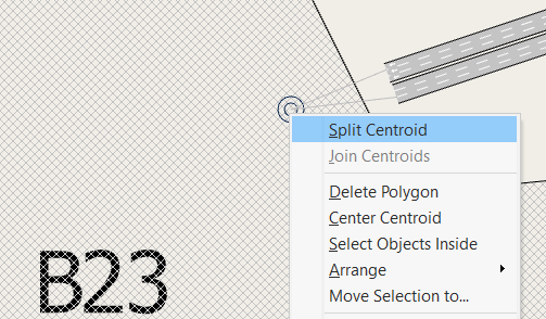
To split a centroid:
- Right-click the parent centroid and select Split Centroid.
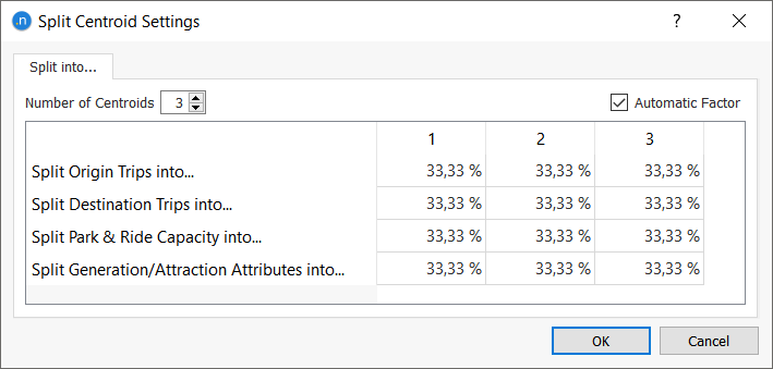
- In the Split Centroid Settings dialog, specify 3 for the Number of Centroids.
-
If you want Aimsun Next to automatically split Origin Trips, Destination Trips, and Generation/Attraction Attributes between the three centroids, tick the Automatic Factor box and go to step 5. If you want to split these attributes manually, do not tick this box.
-
Manually input percentages for each of the three centroids for the following (the percentage in each row must add up to 100%):
-
Split Origin Trips into...
- Split Destination Trips into...
- Split Park & Ride Capacity into...
-
Split Generation/Attraction Attributes into...
-
Click OK to close the dialog and create the three centroids in the 2D view.

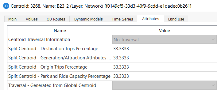
You can now open and edit each of the three centroids individually. Each centroid will now have the corresponding attributes with the percentage that was assigned to each category, for later tracking of the splitting procedure.
Joining Centroids
In addition to splitting centroids, you can also join two separate centroids to form one larger centroid. When joined,all their connections will be merged into one centroid, updating OD matrices and OD routes accordingly.
From Aimsun Next 22 onwards, joining two centroids now accomplishes the following:
- Joins both polygons of the original centroids and associates the new polygon with the new single centroid
- Aggregates the land use dataset attributes of both centroids
- Aggregates park and ride capacity, if available, in the network
- Aggregates the external arrivals and departures of both centroids
- For matrices that are not trips, the process calculates an average value of the original non-trip values.
To join centroids:
- Select both centroids in the 2D view.
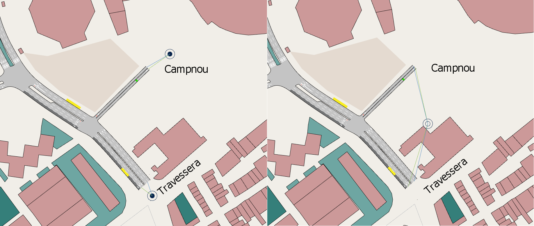
- Right-click on one of the selected objects and select Join Centroids. The screenshots below show before and after images of the process.
- Repeat for any other pairs of centroids.
The merged centroid you have just created now constitutes a single centroid that can be merged with another if required. Open the centroid's dialog to see that it now contains all the connections from both centroids.
Centroid Tesselator
The Centroid Tesselator is available in the menu option: Tools: Centroid Tessellator. It will automatically calculate the centroids polygon for the active Centroid Configuration, resulting in a partition of the area covered by the network. The polygons are calculated according to a Voronoi Diagram, where a point belongs to the polygon of the centroid that it is closest to.
The Tesselator can be applied after the centroid polygons have been edited and after applying the Tessellator, the polygons can then be adjusted manually.