Managing Scenarios
Note about licenses: These exercises require a license for Aimsun Next Pro, Advanced, or Expert Editions.
- Exercise 1. Comparing Scenario Data
- Exercise 2. Overriding Network Attributes
- Exercise 3. Working with Revised Scenarios
- Exercise 4. Using Geometry Configurations
Introduction
These exercises look at different ways of working with several scenarios within the same project.
We will compare data from two scenarios running on the same network. We will create network attribute overrides and work with network revisions that use different geometry configurations in scenarios.
The backup copies of the files related to this exercise are in [Aimsun_Next_Installation_Folder]/docs/tutorials/8_Scenario_Management.
Exercise 1. Comparing Scenario Data
In this exercise, we will compare the results of two different scenarios in the same Aimsun Next model (ANG) file. The differences between scenarios comprise the demand placed on the network and the signal control plan.
- Select File > Open > Initial_Scenario_Management.ang. This model contains a single scenario, a base traffic demand, and two master control plans.
1.1 Varying the traffic demand
For the new scenario, we need to create new traffic demand by copying the existing Traffic Demand.
To create a new traffic demand:
-
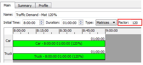
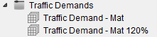
Copy the existing Traffic Demand object and rename it Traffic Demand - Mat 120%.
-
Open Traffic Demand - Mat 120% and change Factor to 120. This increases the number of trips in all OD matrices in the Traffic Demand by 20%.
1.2 Creating a new scenario
Now that we have two Traffic Demand objects, the next step is to create a new scenario.
-
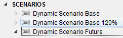
Copy the current Scenario and rename it Dynamic Scenario Base 120%.
-
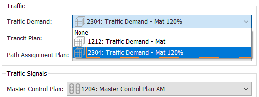
Open Dynamic Scenario Base 120% and for Traffic Demand assign Traffic Demand - Mat 120%.
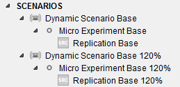
Because we copied the original scenario, its experiment and replication were also copied over. However, the random seed will differ for the replication.
1.3 Comparing results
We can now run the replications and compare the resulting data.
-
Run each scenario's replication and let each run finish.
-
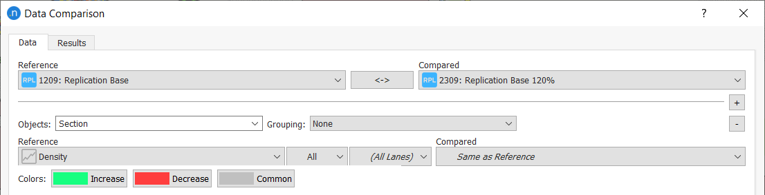
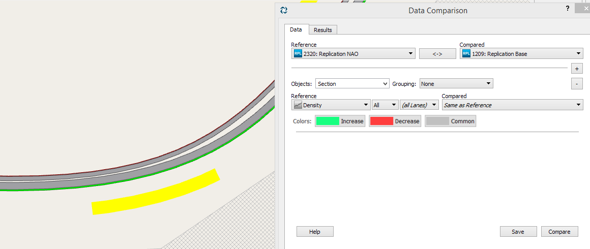
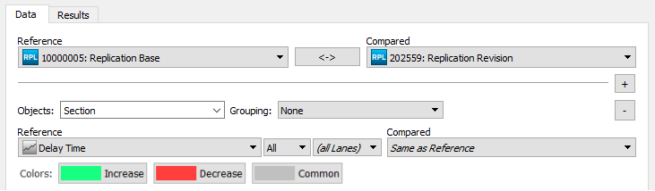
Select Data Analysis > Data Comparison.
We can select four different object types to compare using the Data Comparison tool: Section, Node, Detector, or Turn. Comparison can be made for all objects of a selected type or for a limited selection of the objects.
-
Compare the Density for all sections in the network. To do so, set the fields as below and click Compare.
-
Now select the graphical or numerical outputs, using the Table or Graph icons
 .
.
-
To see the aggregated results in the 2D view instead of results by time interval, click button A.
Results are displayed by data-gathering time period (set on the Scenario dialog > Outputs to Generate tab) or for the whole simulation period.
1.4 Varying the master control plan
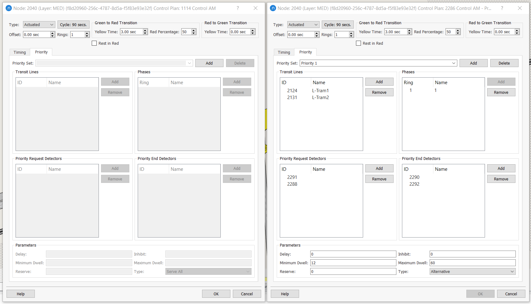
Now we will add different traffic controls to a third scenario. In the ANG file there is a second control plan which features priority for trams at Node 2040.
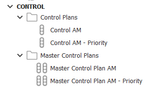
You can see the differences in the Control Plan dialog for the node. To do so, right-click on Node 2040 and select Edit Control Plan > Control AM. Repeat for Control AM - Priority.
To create a third scenario with different controls:
-
Create a third scenario by copying the base scenario and rename it Dynamic Scenario Priority.
-
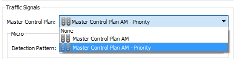
Open the new scenario and for Master Control Plan select Master Control Plan AM - Priority.
-
Run the replication and allow it to finish.
-
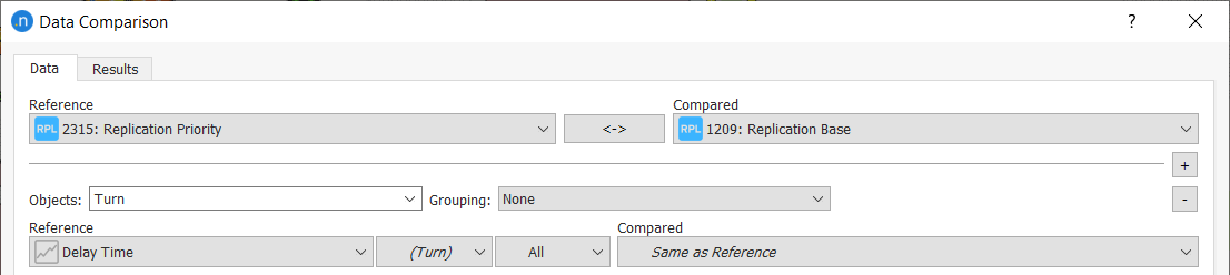
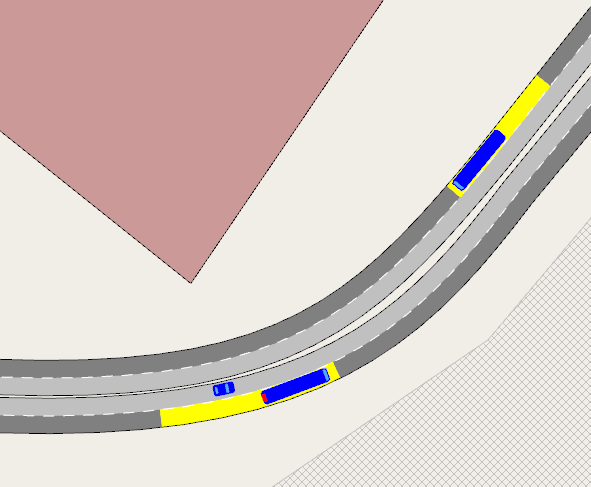
Use the Data Comparison tool to compare the Delay Time for this turn with the turn in the original scenario.
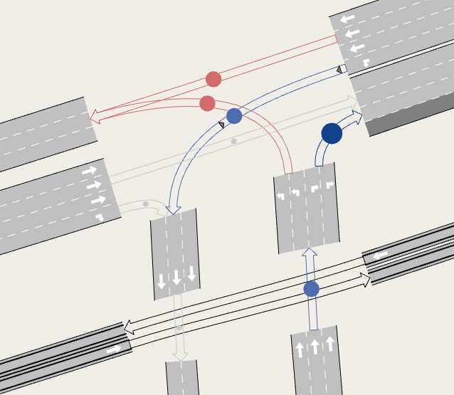
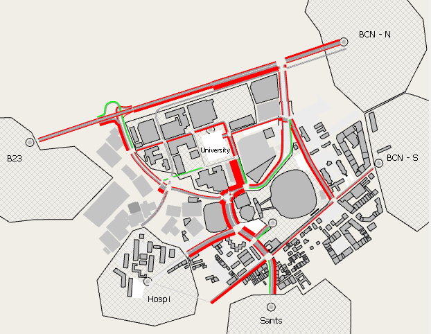
The tram turns are colored blue, which means that the delay time has dropped because the signals give trams priority at the junction. We can see the same statistics visualized in the related sections:
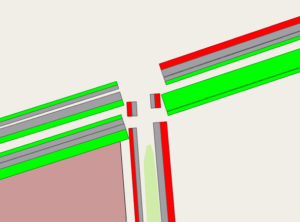
The tram sections are much improved (indicated by green) as are the road sections that coincide with tram movements.
Exercise 2. Applying a Network Attributes Override
The aim of this exercise is to learn how to modify the value of some network parameters without having to create a whole new copy of the network. We will make modifications at the level of the experiment so that we can compare different replications, rather than at the higher level of the scenario as in Exercise 1.
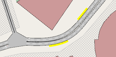
This example will focus on sections 936 and 939. We will change their transit stops from bus-bay types to normal types and designate lanes as reserved lanes. The two transit stops are highlighted in yellow below.
2.1 Changing transit stop types
-
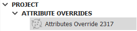
Select Project > New > Attributes Override.
A new object will appear in the Project window.
-
Double-click to open the Attributes Override dialog.
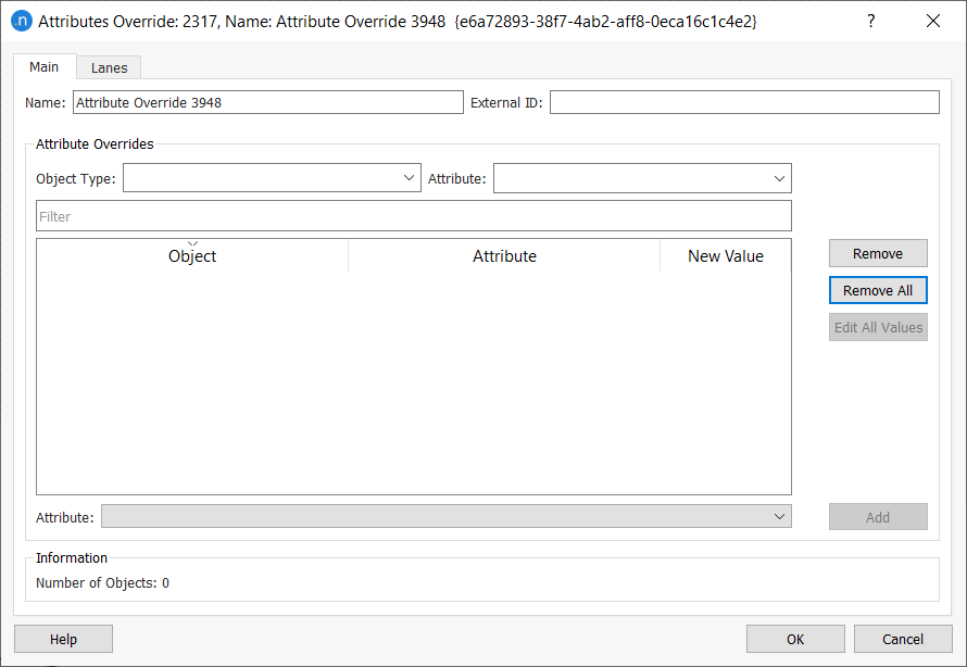
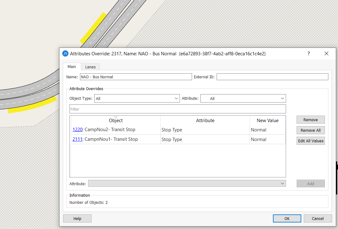
The objects that you can modify are (on the Main tab) sections, nodes, turns, detectors, transit stops, and (on the Lanes tab) lanes.
-
In the 2D view, select Transit Stop 1220 on Section 936.
-
From the Attribute drop-down, select Stop Type and click Add to add the stop to the dialog.
-
Repeat steps 3 and 4 for Transit Stop 2111 on Section 2336.
-
Click Edit All Values and change their type to Normal. This changes the type of stop for both objects.
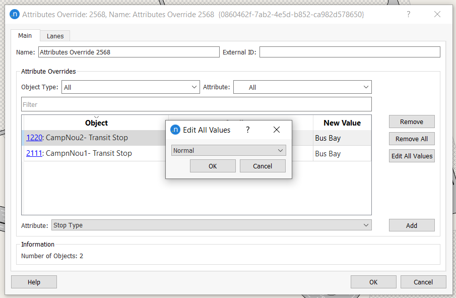
You can also change single objects individually by changing the contents of the New Value cell.
2.2 Applying reserved lanes
-
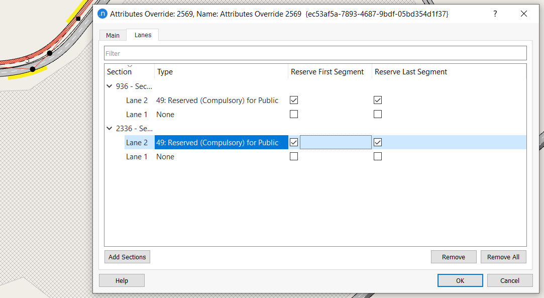
Click the Lanes tab.
-
In the 2D view, select both Section 936 and Section 2336 and then click Add Sections.
-
For both sections, change the Type of Lane 2 to Reserved (Compulsory for) Public, as pictured below.
-
Tick Reserve First Segment and Reserve Last Segment for each section.
-
Click OK to save your changes.
2.3 Assigning attribute overrides to an experiment
You can now assign the modifications specified in the Attributes Override object to a scenario's experiment:
-
Duplicate the base scenario's experiment and rename it Micro Experiment NAO.
-
Open Micro ExperimentNAO and tick the Attributes Overrides option as pictured below.

-
Run the simulation and observe how modifications imposed by the Attributes Override object affect the network.
-
Use the Data Comparison tool to study the effects of the changes in the network. In fact, in network density, very little change is seen.
-
Save this version of the model with the name Final_Scenario_Management.ang.
Exercise 3. Working with Revised Scenarios
This exercise shows how to work with two related networks, simplifying a project that has both a base network and a future network that shares most elements of the base but contains changes to the original geometry.
To relate two networks, both of them must store their data in the same database. Also, to compare scenarios in different networks they must refer to the same database too.
So the first thing to do is to ensure that all data is exported to a common database:
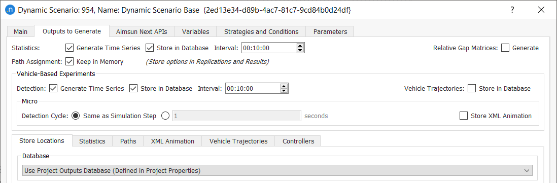
- Open the scenario and click the Outputs to Generate tab.
- On the Store Locations subtab, select Use Project Outputs Database (Defined in Project Properties) from the Database drop-down list.
This current network will be considered as the base network. Run the base scenario simulation to generate data in the database.
3.1 Creating a revision
To create a revision, we must first save the network to avoid losing the last changes made:
-
Select File > Save.
-
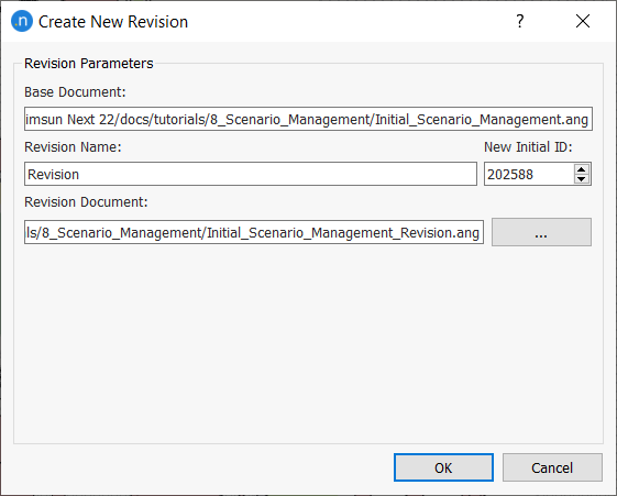
Select Project > New Revision. The Create New Revision dialog opens.
-
Add a Revision Name or leave as is.
-
Click OK to save the new revision ANG file. The current file header is changed to reflect the new name:
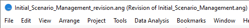
What we have just done is to create a new ANG file (the revision) that is linked to the original base network file. Now that we have two networks, there are two ways to modify them:
Modify the base network. This automatically modifies the revision with the same modifications as the base network.
Modify objects in the revision. The revision file is the only one that contains the modifications. When this network is saved, the modified objects change their state to Revised. Any object marked as Revised will not contain any changes that are made in the base network. Once an object is marked as as such it can only be modified in the revision ANG file.
- Once you have created the revision network, delete the scenario(s) that refer to what was simulated previously in the base network.
-
Create a new scenario and name it Dynamic Scenario Revision.
-
Open the scenario and click the Outputs to Generate tab.
- On the Store Locations subtab, select Use Project Outputs Database (Defined in Project Properties) from the Database drop-down list as described earlier.
- Close the file and exit Aimsun Next.
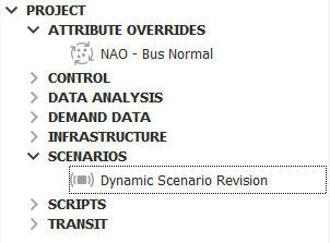
When you restart Aimsun Next the list of existing projects will contain the revision network, marked with a Revision (R) icon:

When you open the revision, you will see a new External Scenarios folder in the Project Window. It contains a scenario that corresponds to the one connected to the base network.
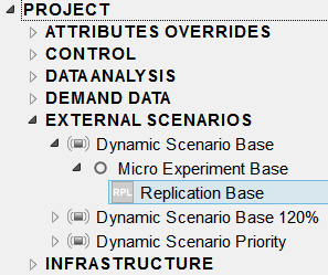
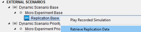
The results for this scenario (which were simulated in the base network) can be retrieved and compared with the results that will be obtained from the revision network scenarios:
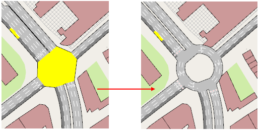
3.2 Modifying geometry in the revision
In this exercise, we will modify the network geometry to transform the signalized intersection into a roundabout as shown in the following image.
-
Delete the node.
-
Select the road sections that previously joined the node.
-
Click
 and drag the mouse to draw the radius of the new roundabout.
 -
Run the simulation.
These new modifications will report problems with transit lines because we added new sections when we created the roundabout. The transit lines will be ignored unless they are fixed by editing them to add the new sections to the route.
-
Click on each affected transit line and add the roundabout sections by selecting the section leading into the roundabout and then the roundabout section that exits onto the next road section. The auto-complete option will add intermediate sections.
-
Run the simulation again to check that transit line errors have been resolved.
-
Save the network file.
After saving, all the sections in the roundabout will be marked as Revised. You can check this in the section dialog header.
Once all the modifications have been made, the two scenarios to be compared are properly defined, and no more modifications are required, you can run the simulations and compare their data.
3.3 Managing revisions
We now have options for how to manage the revision. We can either continue to work with it as a child of the base network or we can separate it as an independent network detached from the base network.
-
Select Project > Detach Revision from Base to copy the base into the revision and make the two independent. The following message will appear.
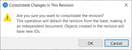
-
Click OK.
The two networks will now be totally independent and any modifications will be exclusive to each file. Both networks can be open at the same time in the same instance of Aimsun Next and the outputs for each network can be loaded independently.
However, with only one network open (both of them will have access to the External Scenario from the other network), you can use the Data Analysis > Data Comparison tool to compare outputs.
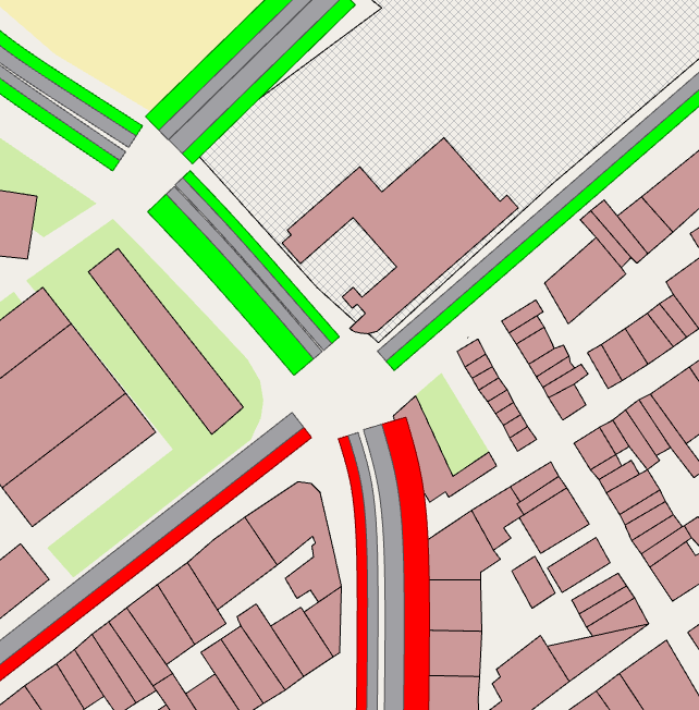
All of the sections common to both networks are visualized in different colors but the roundabout is absent because its sections only belong to one of the two networks. We can see that the delay time of some of the access points has worsened (red) while some have improved (green).
Exercise 4. Working with Geometry Configurations
The Geometry Configurations feature allows scenarios with different geometrical configurations to be contained within the same ANG file.
4.1 Preparing the area of the network to modify
-
Open the file Final_Scenario_Management.ang that you created in Exercise 2.
-
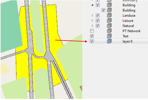
Create a layer named level 0 and set its Level to 0.
-
Right-click on the layer and select Activate.
-
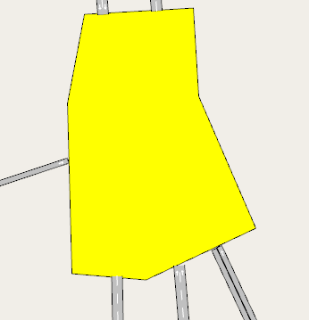
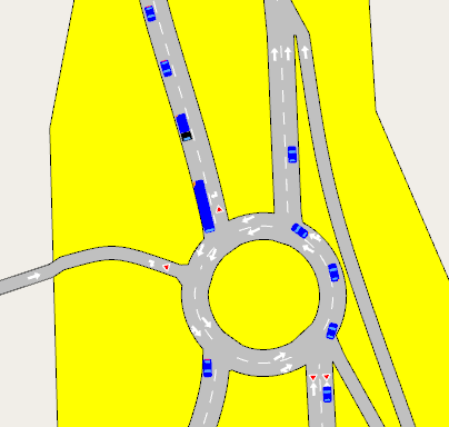
Draw a polygon that roughly delineates the area where we will change the geometry of the network. It will appear to be behind other layers because we set the level to 0.
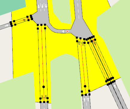
The yellow area pictured below covers the area where we will create a new geometry configuration: a roundabout to replace the current junction.
-
Cut the sections at the edge of the polygon using the cutting tool
 .
.
4.2 Creating the Geometry Configuration
-
In the Project window, select Infrastructure > New > Geometry Configuration.
-
Open the new Geometry Configuration object and click on the Nonexistent Here tab.
-
In the 2D view, select all the objects inside the polygon that will not feature in the new geometry configuration. This means any objects in the base scenario that will be modified or changed.
Just selecting the sections would be enough but we can also mark the nodes. Nodes that fall on the edge of the polygon must not be marked because in the future these nodes will combine the turns of the base scenario and the new geometry, automatically activating some turns.
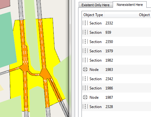
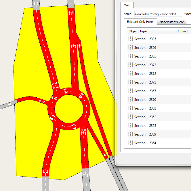
The Nonexistent Here tab should now resemble the screenshot below.
-
Create a new scenario and name it Dynamic Scenario Future.
-
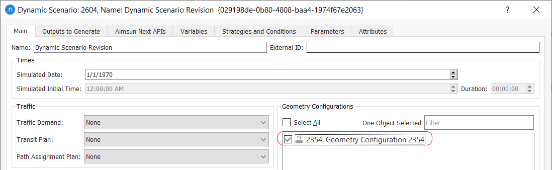
Assign the geometry configuration to the scenario.
-
Go to the Scenarios combo box in the 2D window header and select the newly created scenario.
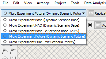
The elements added earlier to the Nonexistent Here tab will disappear from the view.
-
Create the new objects to add the alternative roundabout to the network.
-
When the new road layout is complete, click on the Existent Only Here tab of the Geography Configuration.
-
Select the new road layout objects to add them to this tab. The edge nodes are shared with the base scenario and should not be marked as only belonging to the new geometry configuration.
However, all the new turns in the new geometry configuration that share nodes with the base network should be marked so that they do not appear in the base scenario.
-
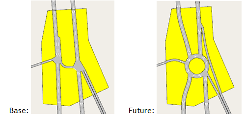
Visualize the two different geometries by changing scenarios in the Scenarios combo box at top-left side of the 2D view.
-
Now launch a simulation using the new scenario and then use the Data Comparison tool to compare the results.
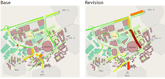
The screenshot below shows a comparison of delay times between the base and future scenarios.
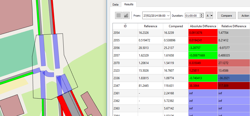
The purple lines indicate that the sections are not present in both of the scenarios being compared because the geometry of the base and future networks have changed at that location.
Therefore, the data comparison cannot calculate and display Absolute Difference – the absolute difference is infinity (inf) in the data comparison table and is highlighted in the same color as the corresponding sections in the network.
Note: Some modifications can affect matrices and control plans, so always check experiments with the Check and Fix tool and read the messages in the Log window at the bottom of the 2D view.