Aimsun Next 3D
An animated 3D view of a traffic simulation is an essential tool in communicating the effects of road network plans to both expert and non expert users. The ability to place the traffic in a recognizable location with familiar landmarks complements the more traditional map based, and graph- and table-based information and builds confidence in the model as being representative of the true traffic situation. Aimsun Next has a strong 3D capability which includes using 3D vehicles, placing objects in the view - either generic building shapes or for landmark buildings, a customized and recognizable shape.
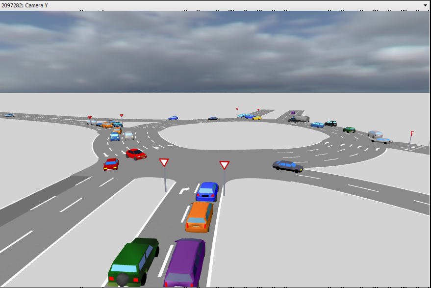
The 3D view adds to the 2D view by using different cameras to provide 3D views into the simulation. Vehicles are rendered using 3D shapes specified in the Vehicle Type Editor and 3D shapes such as buildings, trees, and road signs can be included.
The same options to create video files and to copy snapshots of the images are present in 3D views as they are in the 2D view, however in 3D, there are many more presentation options.
Navigation in 3D views
To navigate in 3D views, the mouse and the keyboard can be used. To use the mouse, then the appropriate icons in the View Commands tool bar must be selected as described in the GUI Section.
3D Pan

The pan tool is used in 3D views to move the 3D view’s active camera to a new location. Alternately the middle mouse button can be used.
-
Moving the mouse with the middle button ( or left button with the pan tool) moves the camera up and down or left and right depending on the mouse movement.
-
Moving the mouse with the Ctrl key depressed at the same time keeps the camera position fixed and rotates the view, either left to right or from vertically downwards to horizontal depending on the mouse movement
-
Using the scroll wheel in 3D maintains the same view point and moves the camera toward it or away from it.
Pressing the Shift key provides another function. Keeping the Shift key pressed, the first mouse movement determines the direction of movement. This means that, for instance, if the desired movement is upwards and any other displacement due to lateral mouse drifts is to be avoided, the way to proceed is to press the Shift key, click on the graphic area and drag the mouse upwards. Maintaining the Shift key pressed will also accelerate the displacement speed of the camera. That is, if the Shift key is hold pressed and the movement is maintained in the same direction:
- moving the mouse
- releasing the mouse’s button when the border of the application window is reached
- moving the mouse to the graphic area again
- pressing and holding the left mouse button
- going back to step 1
the displacement speed will meanwhile also increase.
Moving and Rotating
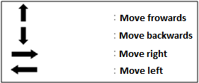
The viewpoint can also be moved using the keyboard arrows and the control and shift keys.
The main camera movements and rotations are movement forwards and backwards and rotation right or left. The arrows used to do this are as follows:
However, for all the movements and rotations to be accessible via the keyboard, the function of the arrows changes depending upon whether the Ctrl or shift keys are pressed.
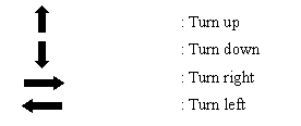
When the Ctrl key is pressed, the arrow keys functions are:
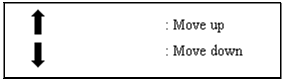
Finally, when the shift key is pressed the arrow keys functions are:
These movements are valid for cameras that allow translations and rotations. When a camera only allows translations, the movements with the keyboard are only translations.
Selection in 3D views
In 3D views, the selection tool is used to open the object editors (by double-clicking on the desired object) and to create and locate a camera inside a simulation vehicle during a simulation. This camera will be updated with the vehicle’s position at every simulation step. To do so, single click on the desired vehicle. Whenever a vehicle with a camera inside leaves the network, the views that have the vehicle’s camera as the current one, change back to the camera that was being used before the vehicle was selected.
Selected objects are drawn with extra red lines in 3D views to identify them.
3D Annotation 
3D Shape Objects
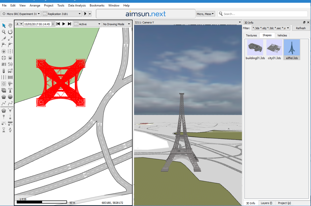
3D Shape objects are decoration objects that can be added to any model to add realism and to identify the modelled area by including a signature building or landmark. To add a 3D Shape object, open the 3D info window, move to the Shapes tab, drag the desired 3D Shape from those available in that tab and drop it into a 2D view.
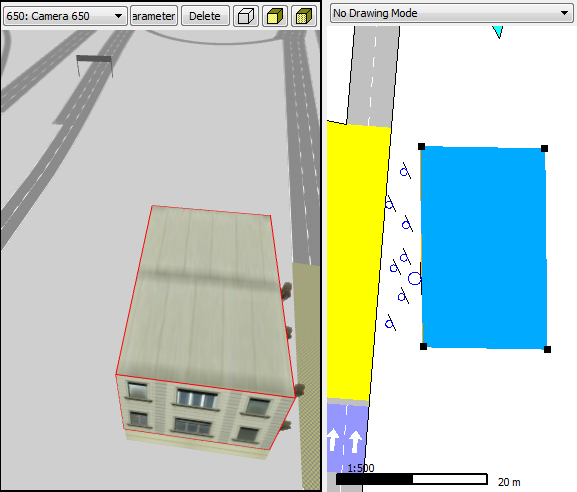
Once the 3D Shape has been dropped, the 3D Shape object will be created. A 2D wireframe projection of the shape will appear in the 2D views and the realistic representation of the 3D Shape will appear in the 3D views
3D Shape Object Editor
Clicking on a 3D shape brings up its properties editor which can be used to change the attributes of the shape as it is positioned in the view.
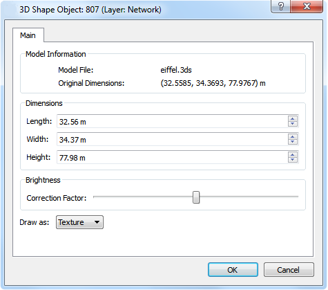
In this editor, the length, width and height of the 3D Shape object can be defined. When clicking on the OK button, this use of the 3D Shape object will be rescaled in all views. A checkbox allows defining whether rendering in 2D will be a box or the 2D wireframe projection of the shape. There is also a slider that overrides the original “brightness” of the 3D model by adjusting its material’s properties. This is useful when imported models, due to differences in lighting between different programs, appear darker or brighter than expected.
3D Images
3D images are used to add objects, such as trees and traffic lights, to make the 3D views more realistic.
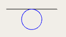
To add a 3D Image, select the 3D Image tool and click on a 2D view. In a 2D View a 3D image is represented using a 2-point segment and a circle on it that indicates the face where the texture will be applied. This segment will become the ‘support’ of the 3D image. Note that if a small image is added while the view is zoomed out, the image might not be visible until the view is zoomed in to a level where the image can be rendered.

The 3D Image tool can be used in continuous mode (by double-clicking on the icon) to add as many 3D images as desired efficiently.
A 3D Image is like a wall but without depth. These images have two main uses:
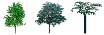
- To add trees to the network. This option is very useful because the TGA files used by images can have a transparent area and then the trees are drawn efficiently (using a single polygon instead of thousands) but realistically using the texture.
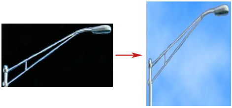
- To add any object (i.e. advertisements) drawn in a TGA or PNG file. This is especially useful when adding textures that have a transparent component. The figure below provides an example of drawing a realistic streetlamp using a TGA texture.
3D Image Editor
Double-clicking on a 3D Image brings up the 3D image Editor.
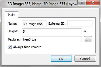
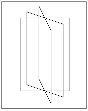
In this editor, the image’s height as well as its texture can be defined. To define the texture click on the texture path button and select it. It also has a check box to set whether the image will always face the camera or not. The image is placed on a rectangle and by selecting this option, the rectangle will rotate as the camera moves in order to be permanently facing the camera so that the face with the associated texture will be the only one seen. In figure below, three different positions of the image can be seen.
A 3D image has an altitude, that is, the Z co-ordinate at which the base of the image will be located. This altitude can be modified by selecting the image in a 2D View and with the Control key pressed dragging the mouse up or down. The current altitude will be shown while dragging. The width of a 3D image can be changed by editing the two segment points that represents it in 2D.
Finally, a texture can be applied without using the editor by dragging the desired texture from the 3D Info Window to the 3D image in either a 2D or a 3D view.
Cameras
A camera is a point used to view the network and the 3D animation in the 3D viewer environment. The number of cameras that can be created is unlimited.
A Camera is created with the Camera Tool and used to select a prepared viewpoint in the model. A camera is also generated if a vehicle is double clicked in a 3D view. This camera is placed behind the vehicle and follows it as it moves through the traffic network.
In a 2D View a camera is represented using the following shape:
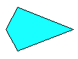
The camera head indicates where the camera is pointing. As with any
graphical object, a camera can be translated by selecting it and
dragging it in a 2D view to its new position. Using the Rotation tool
 , selecting the camera and rotating it in a 2D view can change the aiming point.
Camera Editor
The camera editor will show the camera parameters. The editor pops up by double clicking on a camera in a 2D view and by pressing the Parameters button located in a 3D view (that will open the 3D view’s current camera editor).
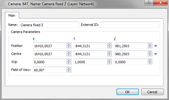
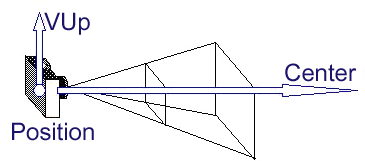
Using the editor, the camera can be renamed and its location parameters can be changed. To rename a camera its context menu can also be used. The parameters that define the camera location and where it is pointing to are:
- Position: Point at which the camera is located.
- Center: Any point in the camera’s vision line.
- VUp: Vector that defines the camera orientation in the plane perpendicular to the Position-Center line.
- Field of View: Changes the degrees of the angular extend of the view that is seen in any given moment.
Camera Commands
In the View menu, there are three commands that apply to cameras:
- Reset camera to place the camera in the active 3D view at its initial position, undoing all the rotations, translations and zooms that it might have undergone.
- Set Camera parallel to floor to set the current camera in the active 3D view parallel to the floor’s surface. This option is particularly useful for fixing the camera’s position from any undesired rotations.
- Set Camera perpendicular to floor to set the current camera in the active 3D view perpendicular to the floor’s surface.
Default Cameras
When a 3D view is opened for the first time, if no cameras exist then four default cameras are created. These cameras are:
- Main Camera: camera located at a default point from where the whole network can be seen. Translations and rotations are allowed.
- Camera fixed X: fixed camera with the view line parallel to the X-axis; only translations are allowed.
- Camera fixed Y: fixed camera with the view line parallel to the Y-axis; only translations are allowed.
- Camera fixed Z: fixed camera with the view line parallel to the Z-axis; only translations are allowed. This camera is similar to the 2D views.
Camera Routes
A camera route is a group of camera positions that will be played and animated in 3D views. Refer to the section on Dynamic Bookmarks for details on defining camera routes.
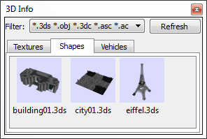
3D Info Window
The 3D Info Window shows the library of textures and 3D models available for the network. It can be shown by accessing the Window Menu, Windows submenu, 3D Info option.
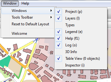
There are three folders in this window:
- The Vehicles Tab: All the available 3DS files to be used as vehicles in the 3D views will be shown.
- The Shapes Tab: All the available 3DS files to be used as shapes, that is, decoration, in the 3D views will be shown.
- The Textures Tab: All the available image files to be used in the 3D views will be shown.
Vehicles Tab
Any simulation can be presented in a 2D View and/or in a 3D view. In 3D views, the simulation vehicles are visualized using a 3DS shape. Refer to the Vehicle Type Editor for details on associating 3DS shapes to vehicles.
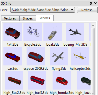
The 3DS shapes that will be shown in this folder must be located in the Program Files/Aimsun/Aimsun Next X.X/shapes/cars folder or in the <network folder>/shapes/carsfolder. The Aimsun Next X.X folder is the folder where Aimsun Next current version ( X.X) is installed and the network folder is the folder where the current ANG file is located.
There is a group of 3DS shapes available with Aimsun Next. However, additional 3DS files can be included by copying them into the system or model folders.
When double-clicking on a vehicle shape in the vehicles tab, the Vehicle's 3D Shape Editor will appear.
Vehicle 3D Shape Editor
The Vehicle 3D Shape editor can be opened by double-clicking on a 3DS Shape in the Vehicles folder in the 3D Info Window. It is used to select the different color sets that the 3DS shape will be drawn with, as well as to define its dimensions, its rotations and its animation parameters if any (see figure below). It also has an online visualization of the shape with the current color set definition.
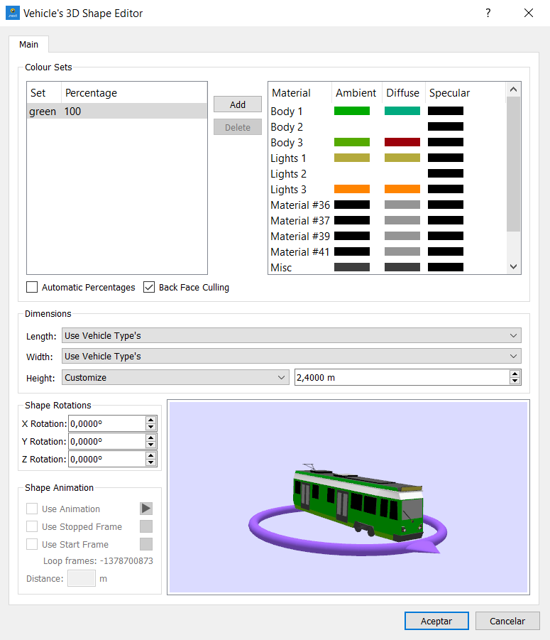
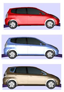
Color Definition
A color set is a collection of colors to be applied to the different parts of a vehicle shape. For example a car might have red, white and gold body paint but it will still have silver wheels and black tires. A color set contains the colors required to draw the car shape and for this example car there might be three sets (red, silver, and black; white, silver, and black; and gold, silver, and black) to draw red, white, and gold-colored cars.
Any number of color sets can be defined for a vehicle shape. The only requirement is that the color set percentages must sum up 100. To define a new color set, press the Add button . This will add a new line in the Set/Percentage column and a list of random colors associated with each of the parts of the vehicle shape in the columns <Material, Color>. The color associated with each material (or part) has three components, Ambient, Diffuse and Specular, which can be changed by clicking on the corresponding colored square when a color picker dialog will appear.
To remove a color set, select it and press the Remove button.
To change the name of the color set, double-click on the current name and enter the new name.
To change the percentage assigned to the color set, double-click on the current percentage and enter the new percentage.
While defining the color sets for a vehicle shape, the Automatic Percentages button can be checked to equally distribute all the color sets’ percentages.
Back Face Culling
Back Face Culling is a 3D optimization where only the outside faces of the 3D Object are drawn. If the normals (a line, ray, or vector that is perpendicular to a given object) of a 3D Object are correctly defined (i.e they all point outwards from the object) then, Back Face Culling can be used and simulation will run faster.
Vehicle Shape Rotations
To draw the vehicles correctly while simulating, the shapes associated to them must be rotated correctly, that is, in the picture of the vehicle shown in this dialog:
-
Its front must face to the right of the dialog.
-
Its upper part must face up.
The following figure displays a shape before rotating it and the same shape correctly rotated with its rotations defined.
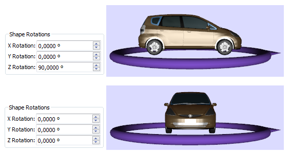
These rotations are expressed in degrees and they can be set using the Shape rotations part of the dialog
Vehicle Shape Dimensions
In the Dimensions dialog section, the real length, width, and height of the shape can be defined. These dimensions are used to scale a vehicle proportionally with a different length than the one specified here.
Camera Displacement
During the simulation, if the user clicks on a vehicle, a camera is placed to allow the user to follow its movement along the network closely.
There are four cameras available that can be selected by using the 1 to 4 number keys on the keyboard, 1 being a camera inside the vehicle, 2 and 3 being cameras located behind the vehicle and 4 being a bird's-eye view that will follow the vehicle during simulation. Once a camera is placed, the wheel of the mouse can be used to adjust the distance to the vehicle in all cameras except the one inside that remains at a fixed location.
Shape Animation
A 3DS shape can have more than one frame to represent movement. If a shape has frames to animate, these can be used in the simulation. The properties found in this group define the shape animation (see next figure).
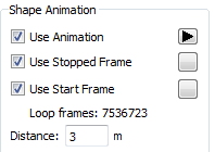
A 3DS shape might have one frame that represents the stop position, another one that represents the starting movement and several more that make the movement loop. Our convention is that the stop frame, if any, is the first frame; the start frame, if any, is the following frame; and finally the rest of frames define the movement.
Then, the properties that can be defined are:
- Use animation: when selected, all the frames will be used in loops during the simulation and when not selected, only the first one will be used.
When this button is pressed  the animation can be seen in the bottom-right section of the Shapes Dialog.
In this case, its shape changes to
the animation can be seen in the bottom-right section of the Shapes Dialog.
In this case, its shape changes to  .
When the button is pressed, the animation is stopped.
.
When the button is pressed, the animation is stopped.
-
Use Stopped Frame: when selected, the first frame will be considered as the stop frame so it will only be used when the vehicle is stopped, that is, the movement loop will not use it. When this button,
 : next to the Stop or to the Start Frame, is pressed, the frame can be seen in the bottom right green square of the Dialog.
 -
Use Start Frame: when selected, the second frame will be used whenever the vehicle needs to start its movement, that is, the movement loop will not use it.
- Distance: here the user sets the distance that the shape will cover when moving from the first animation frame to the last one.
Vehicle Editor 3D Shapes folder
In the Vehicle Types Editor , there is a tab to define the multiple 3DS shapes that will be used in 3D views to draw the simulated vehicles of that vehicle type. The shapes are organized by length range so that if for example a car vehicle type was to be defined in the Vehicle Types Editor to have a length between 3.5m and 4.5m then using the example below; the shorter vehicles would be visualized with one of the Hinda, Isuzu or Mercedes shapes and the longer vehicles as a BMW or a Nissan.
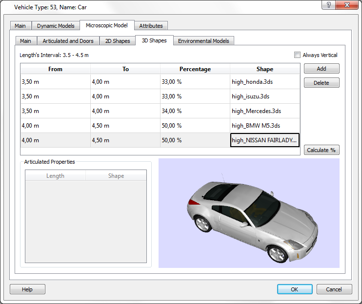
The Calculate % button distributes the shapes equally in each interval if a uniform distribution is required.
The Always Vertical option ensures that objects (vehicles and pedestrians, when relevant) keep their vertical aspect when moving on slopes. This should be unticked for road vehicles to ensure they follow the gradient as expected. It should be ticked for pedestrians, so that they move realistically, at the correct angle, for example when moving up and down stairs.
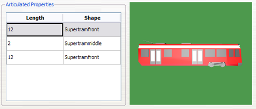
Articulated Vehicles
An articulated vehicle is a vehicle that has a set of shapes connected one after the other (see the example in figure below).
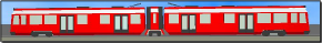
The shape used to visualize an articulated vehicle is assigned by vehicle length as for non-articulated vehicles but in the 3D shape editor, multiple sections are required with length specified for each separately.
Shapes Tab
The shapes used in 3D views as decoration objects will be shown here. In order to use any 3DS file as shape they need to be located either in the <AIMSUN_HOME>/shapes folder or in the <network folder>/shapesfolder. As with the 3DS files used for vehicles, additional 3DS files can be included by copying them into the system or model folders.
The newly added shape will use the dimensions defined in the 3DS file or if these have been overridden in the 3D Shape Editor then the user supplied dimensions will be used. Dimensions for this specific use of the shape which override the allocated defaults can be supplied by opening the 3D Shape Object editor (double click on the 3D Shape Object).
When double-clicking on a shape in the Shapes Tab, the 3D Shape Editor will appear.
3D Shape Object Editor
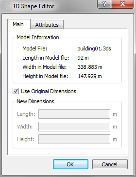
In this editor, the length, width, and height defined in the 3DS file are shown. The defined dimensions can be used when adding a shape to the model or these can be overwritten by checking or unchecking the Use Original Dimensions option. When unchecked, a new length, width, and height can be defined. These values will be the initial dimensions of the shape when added to any model.
Textures Tab
The textures that can be used in 3D views will be shown here. Image formats available to be used as textures are JPG, PNG, TGA, and GIF files. Textures can be applied to the sky and floor, to polygons, to blocks (or extruded polygons) and to 3D Images.
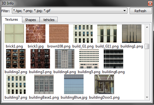
The images to be used as textures must be located in the <AIMSUN_HOME>/shapes/textures folder or in the <network folder>/shapes/texturesfolder.
As with the 3DS files, additional textures can be included by copying them into the system or model folders.
When double-clicking on a texture in the Textures tab the Texture Editor will appear. There, all the texture parameters can be defined.
Texture Editor
When double-clicking on a Texture in the Textures tab of the 3D Info Window the Texture Editor appears.
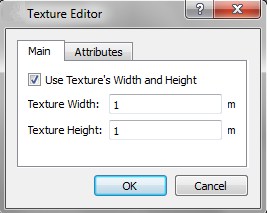
Using this editor, a width and height for the texture can be defined. When a texture has a width and height defined and the Use Texture's Width and Height option is checked, then the texture will be scaled following these dimensions whenever applied into any object and it will be automatically replicated. If the Use Texture's Width and Height option is not checked then the texture will be scaled following the number of horizontal and vertical repetitions defined. Refer to the Polygon Editor and the Extruded Polygon Editor sections for more details.
Atmospheric Effects
Atmospheric effects is an extension of the microscopic simulator that enables the visualization of rain or snow in the 3D view when an animated microscopic simulation is running.
The extension is enable in the scenario editor in the API tab where double clicking the extension brings up a control dialog.
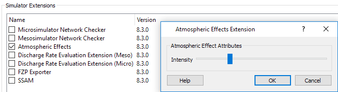
When enabled, the extension takes the weather parameter from the Parameters Tab of the Dynamic Scenario and activates the rain or snow effects in the 3D view when weather conditions are set to "Rainy" or "Snowy".