Annotation
Text, lines, and polygons are used to annotate a model to add to the visualization of the simulation and to assist the stakeholders viewing the model to understand what it is showing and provide location references.
Much annotation is provided by the Network Background imported from a GIS, from an aerial photograph or from OpenStreetMap. This section of the manual covers editing customised ( i.e. manually created) objects, although note that annotation imported from external sources is simply formed of the same basic text, lines, and polygons and (once editing is allowed in the imported graphical layers) these objects can be edited in the same way, with the same tools.
The annotation creation tools are found in the drawing window toolbar.

Text 
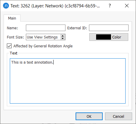
Text annotation is added by selecting the text tool in the toolbox and clicking in the drawing window to bring up the dialog to enter the text, the label for the object and its size and color. There is an option to rotate the text in line with the 2D view rotation angle (set in Preferences section ) or to keep the text at a constant angle independent of the view.
Line Editing
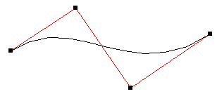
There are two tools to create lines. The Polyline tool is used to create lines with straight segments, the Bezier Line tool to create curved lines. To create a line select the tool and click in the drawing window to add points. Double click ends the line creation, ESC abandons the line creation. To edit the line, select a vertex and move it, curved line segments have an additional control point for each segment to adjust the curvature of the line.
Once a line is created, new vertices can be added using the new vertex tools for straight and curved lines, a second curve control point can be added to curved lines and lines can be divided with the cut tool.

To add a new vertex, curve point or to cut a line:
- Select the line in the drawing window
- Select the new vertex tool
- or
- Select the new curve point tool
- or
- Select the cut tool
- With the left mouse button, draw a line that intersects a segment of the selected line
- Release the left button to add the vertex, control point, or to split the line.
Note only two curve control points are allowed per segment. Adding a third curve control point to a line segment will split the line into two segments.
Convert to Section
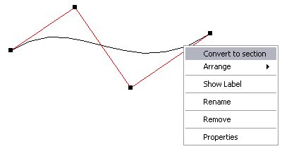
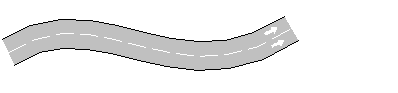
A line can be converted to a road section using the Convert to section option in the context menu.
Line Editor
The line editor is used to change the values of different attributes for a single line.
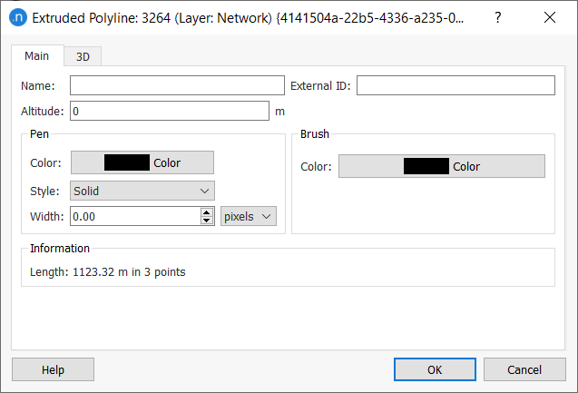
The following parameters can be edited:
- Object Name:
- External ID:
- Altitude: The height at which the polyline will be located
- Line Color: Color used to draw the polyline in the 2D View
- Line Style: Solid, dash, dots or a combination
- Line Width: Either in meters, feet or pixels
- Brush color: For extruded lines only.
Polygon Editing
Polygons are included in the model using the Polygon Tool. To create a polygon, click on the tool, then click on the view to add vertices to the polygon. A double click ends the polygon connecting the last point with the first one, ESC abandons the polygon Once a polygon has been created, new vertices can be added using the New Vertex Tool in the same way as vertices are added to lines.
Circles are created using the new circle tool, click on the tool then click in the drawing window to position the center, drag the mouse to the correct radius and click again to complete the circle.
Polygon Editor
The polygon editor is used to change the values of the attributes of a single polygon. Note that lines and polygons grouped in a drawing layer can have their default drawing style changed together.
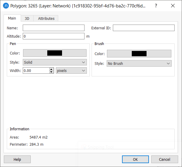
The Main tab controls the 2D attributes of the polygon
- Object name and its external ID:
- Altitude: The distance to the Z = 0 plane at which the polygon will be located
- Line Color and Line Style: For 2D views
- Brush Color and Brush Style: For 2D views
- Line width: In either pixels, or meters.
To change the altitude of the polygon, click the mouse left-button inside the figure then, while pressing ctrl key, move the mouse up or down to increase or decrease the altitude of the polygon respectively. Similarly the altitude of any vertex of the polygon can be modified by using the same mouse controls over the selected vertex. Note that the altitude is set relative to the minimum z coordinate of the vertices in the polygon.
The 3D tab defines the textures applied to the top and bottom of the polygon in 3D views or clears the current texture and reverts to the polygon brush color. The number of texture tiles used to cover the polygon is also set here.
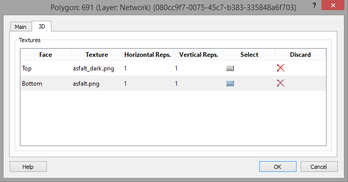
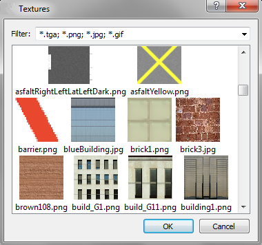
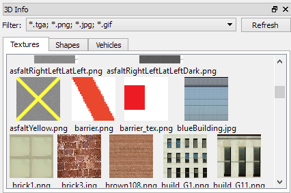
Selecting a texture is done though the textures editor where all the available textures will appear. These are stored in the Program Files/Aimsun/Aimsun Next X.X/shapes/textures folder for all models or in the <network_directory>/shapes/textures/ folder for textures specific to this model.
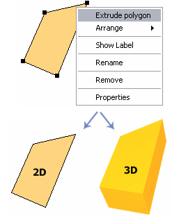
Extrusion
Both lines and polygons can be extruded to convert them into a 3D objects using the Extrude polyline or Extrude polygon option in the context menu. The 3D tab in the object properties dialog is then extended to define the height of the extruded object and textures used in 3D views.
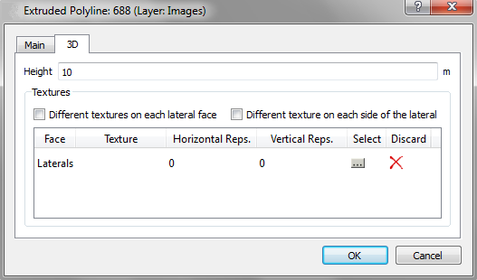
3D Annotation
The 3D tab is used to set:
- The block height
- Whether to set different textures for each lateral face or one for all lateral faces for a polygon
- Whether to set different textures for each side of the lateral for extruded lines.
Textures for the lateral surfaces are selected using the textures editor as for the top and bottom of a polygon When the user has opted for different textures in the lateral faces, a line for each face appears and when selecting one of these lines in the drawing window or in the 3D tab shown here, the two vertices that define the face will be drawn in red in the 2D views.
Textures can also be assigned to a polyline or polygon by selecting the desired texture in the 3D Info window (see the section 3D Info Window for more details) and dragging it over the polygon either in a 2D or 3D view. When dragging a texture without any other key pressed, the texture will be applied to all the faces. If it is dragged with the Ctrl key pressed then it will be applied to only the selected face.
To change the height of the extruded polygon, click the mouse left-button mouse inside the polygon then, while pressing ctrl key, move the mouse up or down to increase or decrease the height respectively. Similarly, the height of any vertex of the extruded polygon can be modified by using the same mouse controls over the selected vertex. Note that the height is evaluated by the distance between bottom face z coordinate to the minimum vertex z coordinate of the top face. The bottom face z coordinate is indicated by the altitude.