Preferences
Preferences control how some of the user interface features operate and how some editing defaults are set.
Preferences are stored at two levels: System and Project.
Preferences at System level are common to all the projects that Aimsun Next will create and open. Preferences at Project level are only valid for the currently open model in which they are set. Some preferences only apply at system level, as they are not related to any particular model, for example, the number of last opened files to be remembered and shown in the File menu. Other preferences should be set for each particular project, for example, the road side for vehicle movement. Different projects can have different values for the same preference.
Both levels are accessible from the Preferences command in the Edit menu. When no Aimsun document is open, this command will be used to edit the preferences at System level. When a project has been loaded, the command will edit the model preferences.
Preferences Editor
General Preferences
- Use Auto Save: When checked, a copy of the current file will be saved periodically with extension ANG.AUTO. The time interval between saves is defined in the Auto Save Time (in minutes) option. In order to set this as the current version, just rename the current document and delete the AUTO extension from the auto saved file.
- Ask for a new name after creating non graphical objects: Whenever a new object is added to the project window, a dialog will pop up to rename the object.
- Files in Open History. A system preference to define the number of documents previously open to be shown in the Welcome Window.
Localization Preferences
- Units: Switches between the metric or imperial (English) system.
- Rule of the Road: Used to indicate which side of the road the traffic drives on.
- North Angle: Indicates the angle (in degrees) between the horizontal line, that is, the positive X-axis, and the North direction of the network. There is no need to fill in this preference as in Aimsun Next, it is only used for information purposes.
- Latitude and Longitude: Defines whether the Latitude and Longitude will be shown as a decimal or using the degree notation. Note that Latitude and Longitude will be shown in 2D Views instead of the UTM coordinates when the option Show Latitude and Longitude in the View Menu is ticked.
- User Interface Language: Allows the user to select the language used by Aimsun Next. It can be set to automatic, which will select the operating system language, or set to any of the languages available in the drop down list. It is a system preference thus only available when no project is open.
- Regional Settings: Allows users to specify the Country and hence the Language . This is used to display numbers, dates, etc. in the expected format.
Nodes Preferences
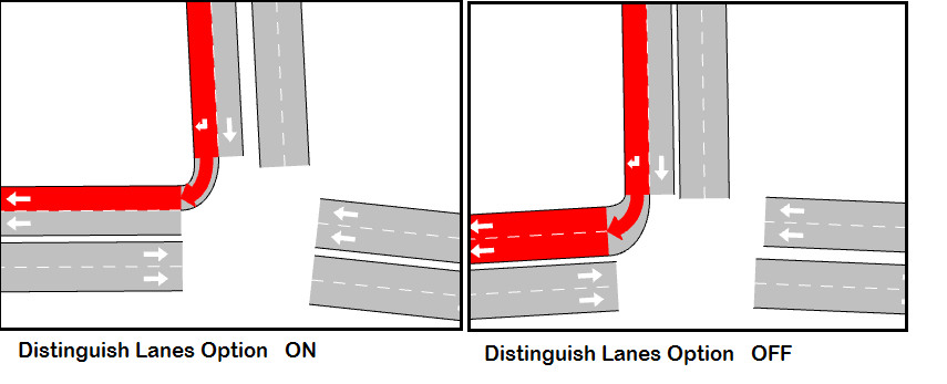
- Distinguish Destination Lanes in Turns: When turns are created at an intersection this option determines if all lanes in the destination section are selected by default or if they must be selected individually. If this option is on then more control over how lanes are linked at an intersection can be exercised as the intersection is created. Adjustments to lane connections can subsequently be made with the Node Editor.
- Default Road Type for Roundabouts: Indicates the default road type of the internal sections of a newly created roundabout. If none is selected, the default road type will be used. It is available only as a model preference as it cannot be certain that all models will include the preferred road type.
Oracle Preferences
- Enable logging in insert and delete: This option enables logging when inserting or deleting data in an Oracle database. Unchecking it will speed-up the operation and minimize the log usage.
Do not uncheck this option unless using an Oracle database. Doing so will make the operation fail.
2D Preferences
- Background Color: Used to define the color of the network background.
- Altitude Increment: The minimum increment applied to the Z component of a selected vertex, when the altitude is changed by pressing the Ctrl key and dragging the mouse in a 2D view.
- Side Lane Size Factor: Used to calculate the inclination of the end or beginning of a side lane. 0.5 is the default value that will result in a 45º angle when drawing the end or beginning of a side lane.
- Rotation Angle: Defines a rotation angle, expressed in degrees, to be applied in the 2D views to the graphical objects. Currently, this rotation is not applied to the images or to any background.
- User Icon: The path to an image that will appear at the bottom right of the view as a corporate logo. This can be used to brand snapshots and videos in presentations.
3D Preferences
Used when drawing objects and animating the simulation in 3D views.
General
Used to select whether to draw:
- sections
- blocks
- nodes
- yellow box nodes as normal or yellow
- incidents
- vehicles as boxes or as 3D models
- traffic signals
- road signs.
Advanced
-
Light: Used to define the intensity of the ambient, diffuse and specular components of the lighting system. The range is 0 - 255, where 0 is dark and 255 light
- Ambient light simulates the light that comes from every direction, lighting every face of the objects whether those are facing the direction of the light or not. Diffuse light represents the direct component of the light, that is, the one that comes from a light source and only illuminates the light-source-facing areas.Specular light simulates the reflective intensity of shiny and glossy areas.
-
Sky and Floor
- Sky Color: The color used to draw the sky when not using a texture.
- Sky Texture: The texture that will be applied to the sky. To define a texture, click the button located at the right of the line and a file dialog will appear. It is only valid to select a texture file from the Program Files/Aimsun/Aimsun Next X.X/shapes/textures directory or the <network_directory>/shapes/textures directory.
- Floor Color: The color used to draw the floor with when not using a texture.
- Floor Texture: The texture that will be applied to the floor; selected in the same way as selecting the sky texture.
-
Simulation
- Ramp meter as Barrier; Moving Time: In 3D views, a ramp meter can be drawn as a traffic light or as a barrier. For a ramp meter with the barrier drawing chosen (see Meter Editing section for details), the number of seconds it takes the barrier to move from the horizontal position to vertical is defined here.
- Position Traffic Lights after Intersections: Locates the traffic lights before or after or the intersection where vehicles stop.
-
Fog
- Use Fog: Selects whether or not fog is incorporated in the visualization. When the user chooses to use fog by checking this option, fog properties can be set. These properties are:
- Fog Color: Clicking the color button brings up a color selectin dialog where the fog color can be selected.
- Fog density: A value that indicates the fog density used in the fog equation. The fog equation is:
f = e - (density\*z)

where
z is the distance in eye coordinates from origin to the object.
- Use Fog: Selects whether or not fog is incorporated in the visualization. When the user chooses to use fog by checking this option, fog properties can be set. These properties are:
Microsimulator Preferences
These are described in the Microsimulator Preferences section.
Adaptive Control Interfaces 
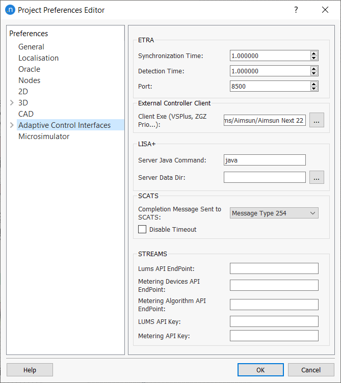
The Preferences Editor) is used to configure the options used in making links to adaptive signal controllers.are described in the Adaptive Control Interfaces section. These include:
- ETRA: Specific parameters for the ETRA controller
- External Controller Client: A path to the external controller, where this is not specified more explicitly for a particular controller.
- LISA+: The command used to start the java emulator and the location of the control data.
- SCATS: Message types and log folder for the SCATS interface.
CAD Preferences
- Retrieve OFF Layers: When retrieving a CAD drawing, this preference controls whether layers marked as OFF (non-visible) will be retrieved.
- Fast Draw (makes layer opaque): When selected, the CAD layer is made opaque to increase the speed when being drawn/redrawn.
- Deviation: A higher value lowers the quality but increases the drawing speed. By default it is 0.000001 and only needs to be changed if the zooming or panning in a 2D View is unacceptably slow when the background is being drawn. The recommended value in that case is 1.