Aimsun Next: SCATS Interface
Architecture
The communication is between Aimsun Next and WinTraff. Wintraff is software that emulates the operation of up to 250 SCATS compatible traffic signal controllers, developed by the Road and Maritime Services organization in NSW Australia. This interprocess communication uses a client server model where the communication channel is made using sockets (TCP/IP) with Aimsun Next acting as a server and the WinTraff process, acting as a client.
Relationship between Aimsun Next objects and SCATS objects
To guarantee correct connection between Aimsun Next and SCATS, it is essential that the SCATS objects such as signals and detectors correspond with the Aimsun objects. Therefore the following rules must be adhered to for intersections, signals, detectors, and the signal control plan.
-
SCATS Intersections: Each SCATS Intersection has to be represented in Aimsun Next as one SCATS type controller.
-
One SCATS intersection can be represented by one or more Aimsun junctions. The SCATS controller must be connected to all Aimsun junctions that form the SCATS intersection.
-
SCATS Signal Groups: The Aimsun model must contain the same signal groups definition as the SCATS model with the same turns associated.
-
Each SCATS detector must have a corresponding detector in the Aimsun model.The modeled detector must have, at least, Count and Occupancy as measuring capabilities.
-
For each intersection controlled by SCATS,the control type must be set to External and a pre-timed or fixed control plan provided with the definition of all phases and their duration.
SCATS Detectors
SCATS has two types of detectors:
- Physical detectors: which measure “count” and “occupancy”.
- Logical detectors (beacons): they identify Transit Vehicles and are associated with one physical detector and a set of transit lines.
Each physical detector in SCATS (physical detector itself or the physical detector associated with one logical detector) has to be modeled as one detector in the Aimsun model. If this detector corresponds to one physical detector then the modeled detector must have, at least, Count and Occupancy as measuring capabilities and if this detector represents one physical detector associated with one Logical detector then the modeled detector must have, at least, Equipped Vehicle as a measuring capability. All transit lines associated with Logical detectors have to be modeled as Transit lines with 100% Equipped vehicles in the transit Vehicle Types.
Note that detector length is strongly related to the Occupancy measured. The modeled detector length should be adapted to match the expected SCATS occupancies.
Debugging
The SCATS interface can be configured to produce debugging information. This option is selected in the Scenario Editor.When this option is active, Aimsun Next will generate log files stored in the same folder as the Aimsun Next document. The file names are (where X represents the communication port of the controllers).
Additional debug output from a SCATSim controller can be generated and subsequently used as input to a SCATS controlled junction to replay the same signals pattern, without linking to SCATSim. This is documented in the Controller Section. These log files will be created in the folder holding the model ANG file and named prefix + _id.txt where id is the SCATS Intersection ID.
Aimsun Next - SCATS interchange information
Aimsun Next provides SCATS with the detector actuation data at each simulation step and SCATS responds with the changes of signal group states, assuming at the beginning of the simulation all signal groups are in red. To ensure that Aimsun Next and SCATS remain in step, synchronization tokens are passed between them every simulation step. SCATS assumes a data transfer is made every second and 1 second of data is available from the detector The detection cycle should therefore be set to 1 second. If the simulation step is not 1 second, the data is sent as soon as possible following the data synchronization rules
There are a couple of preferences that can be set in the Adaptive control interfaces preferences to set the completion message sent to SCATS and whether to disable timeout.
SCATS objects definition in Aimsun Next
The definition of the SCATS objects specifies one SCATS controller in the model for each SCATS Intersection. The Adaptive Controller editor for a SCATS controller is shown below.
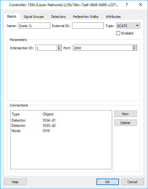
In the Basics tab the options are:
-
Intersection ID: The SCATS intersection Identifier corresponding to the junction linked to this controller.
-
Port: This communication port number defines the communication between Aimsun Next and the SCATS (this is common to all SCATS controllers).
-
Connections: Defines the connections between the controller and those devices under its control. Links are made using the New button or the Connection tool. All nodes and detectors controlled by the SCATS Intersection must be connected.
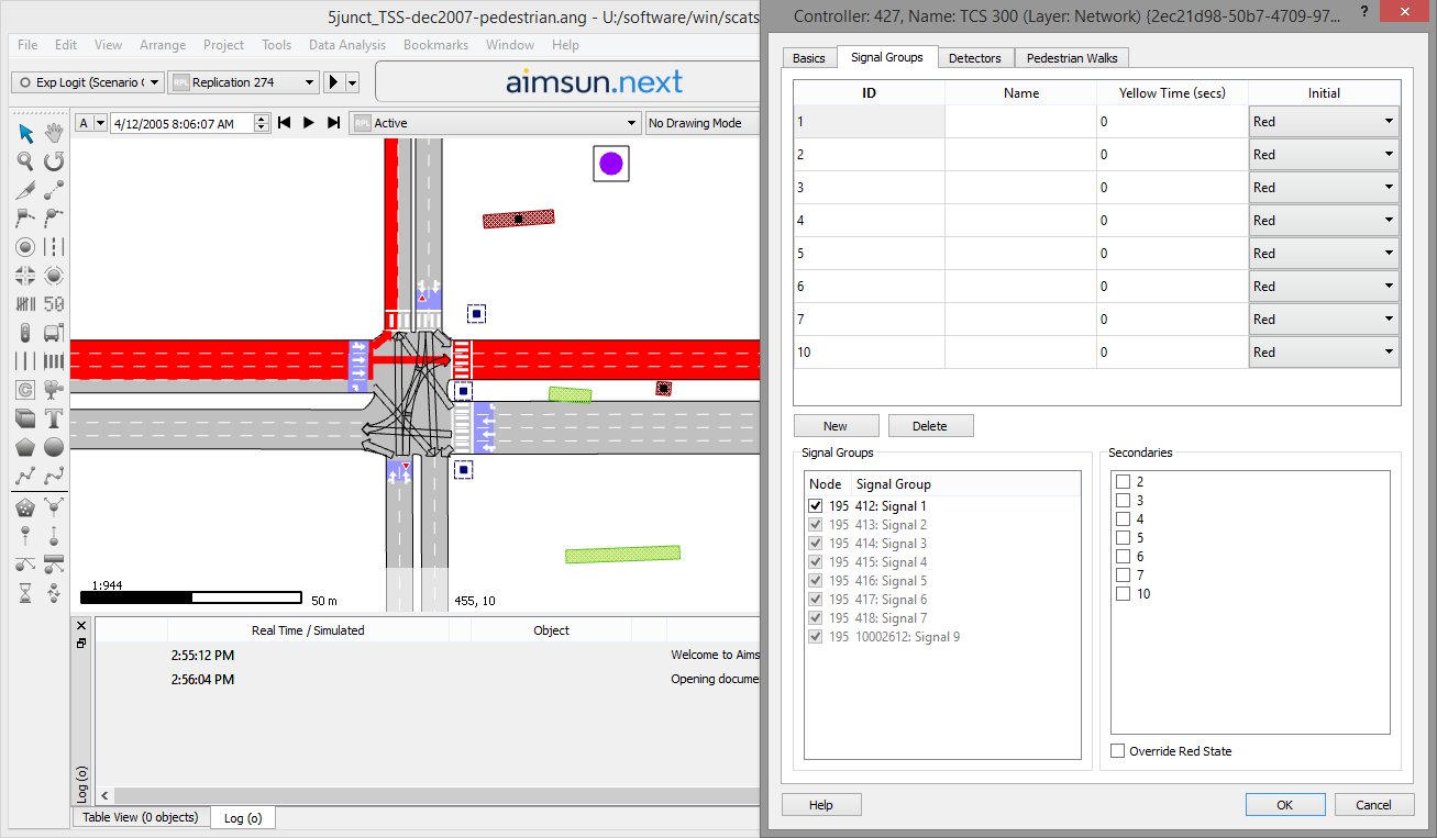
Signal Groups Tab
The second step is to establish how the controller ‘sees’ the different signal groups. Each SCATS signal group has:
- ID: is the SCATS signal group identifier. In one controller these identifiers have to be consecutive and start from 1. These identifiers determine the order how Aimsun Next receives its state and this order has to be the same as SCATS has in its configuration.
- Name: is the SCATS signal group name (optional).
- Yellow Time: is not used.
- Initial: is the initial state of the SCATS signal group at the beginning of the simulation.
Secondary signal groups can be assigned to a signal group.
A set of Aimsun signal groups can be associated with a single SCATS group so they can be controlled together. The example below shows signal with SCATS ID 1 linked to signal group 1 in the simulation.
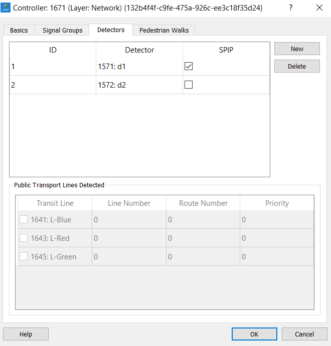
Detectors Tab
The third step is to establish the controller's links to the associated detectors. To add a new SCATS detector:
- Click on the New button.
- Set the ID.
- Select a detector from the list of detectors connected to the controller.
- Select the checkbox if the detector is configured as SPIP.
Each SCATS detector has as attributes:
- ID: represents the SCATS Identifier. A unique integer > 0. Note these do not need to be consecutive numbers.
- Detector ID and Name: the detector in the model associated with this SCATS detector.
- Transit Lines Detected: defines the transit lines associated with one Logical detector (a beacon in SCATS; if the SCATS detector corresponds to a physical detector then no transit lines are selected). In this type of detector, Aimsun Next then sends the Transit Vehicle Information in Vehicle Tracking message.
The example below shows detector with SCATS ID 4 linked to "d6" which is highlighted in the 2D drawing window.
If a beacon is associated with one SCATS intersection (connected with a set of physical detectors), then the Beacon Identifier cannot be the same as another physical detector of the same intersection. For example, if the SCATS intersection 100 is connected to physical detector with 1 as SCATS id, then is not possible to have defined in the same intersection a SCATS Beacon with 1 as Identifier. One solution is to create a fictitious SCATS controller only connected to detectors associated with SCATS beacons, without a junction in the model.
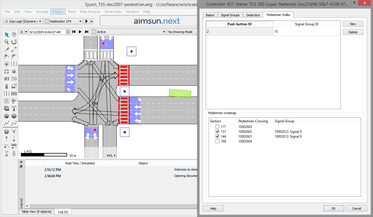
Pedestrian Walks Tab
The fourth step is to establish how the controller ‘sees’ the different pedestrian walks. To add a new SCATS pedestrian walk correspondence, click on the New button and then set the Push Button ID, the signal group associated with this push button ID and select the pedestrian crossings associated with this push button from the list.
Mesoscopic Simulation
Using SCATS with the mesoscopic simulator is possible but there are limitations in the detector information which must be considered. See the Mesoscopic Detector Emulation section for details.
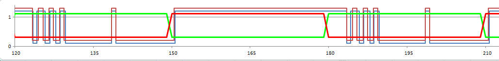
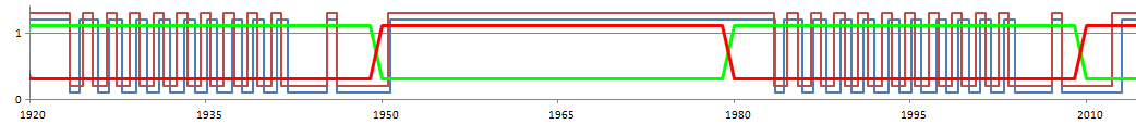

The figure above shows the comparison of meso and micro detection profiles in two different periods of the simulation (different degrees of saturation): 300 veh/h above and 700 veh/h below.
The following observations can be made:
- The first vehicles that cross the detector at the beginning of the green are part of the queue discharge process.
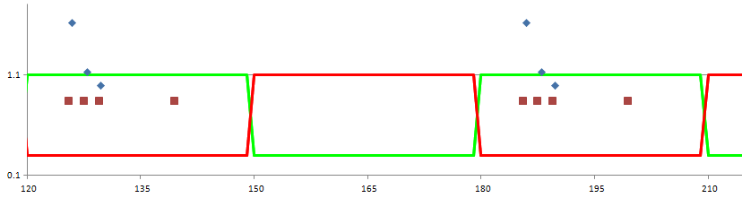
- During this period the occupancy in micro is higher than in meso because vehicles in micro accelerate while in meso they are either stopped or moving at free-flow speed; hence in micro they cross the detector at a speed lower than the free-flow, producing occupancies higher than 0.85 s (starting from 1.6 s and progressively decreasing as the vehicle was back in the queue because it has had more space to accelerate), while in meso they cross the detector at free-flow speed, producing occupancies of 0.85 s. The graph comparing occupancy is below.
- During this period the gap in micro is shorter than in meso and progressively increases toward the value of 1.15 s, which is constant in meso.
- Once the queue is dissipated, vehicles travel under unconstrained conditions for the rest of the green time.
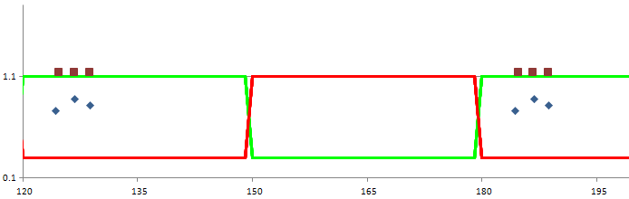
- During this period the occupancy profiles are exactly the same and equal to 0.85 s because in micro and in meso the vehicles cross the detector at the same speed, equal to the free-flow speed.
- During this period the gap is the same in micro and in meso, and depends only on the demand level (shorter the higher is the demand).
- Because in this model the detector is at the very end of the section and it is shorter than the effective length of the vehicles, only one vehicle can be stopped on top of it, so bridging is not possible, neither in meso nor in micro. If we move the detector back by more than 0.5 m, then the first two vehicles in queue when the signal is red would be on top of the detector in micro, producing bridging; however, meso would consider the detector as placed at the very end of the section, and would not observe bridging, therefore the difference between meso and micro would be bigger.
In situations where there is an increasing congestion in downstream sections from the SCATS node, the mesoscopic detection emulation can produce higher occupancy profiles compared with the microscopic simulation. This is due to the fact that vehicles in meso pay the delay caused by lane changing downstream before exiting the section where the detector is located. The gap is not affected, but the throughput (number of vehicles that exit per cycle) is reduced. In order to reduce this effect the recommendation is to cut the sections downstream and calibrate the length of the sections that have been cut and the look-ahead turn distances to avoid vehicle lane changes in the sections after the junctions that have the SCATS controllers.