Detectors
There are many types of roadside detectors: pressure, magnetic, loop, video, and others, but while the detector technology is different, all of them have similar measuring capabilities. These include vehicle count, presence, speed, occupancy, density, headway and, if the detector is suitably equipped, whether the detected vehicle is instrumented and more information made available. Aimsun Next implements generic detectors where the detection technology is not modeled, but the detector data is provided.
A detector in an Aimsun model can be positioned at any point in a section, and its width can extend to more than one lane. A section can have any number of detectors, the only restriction is that a detector cannot be shared by more than one section. A detector will always distinguish between different Vehicle Types.
Detection Cycle
The detection cycle is the timestep at which a detector gathers information. It can be set to be the same as the simulation timestep. In this case, Detectors will be updated at the same time as the simulation. In some cases however, such as when dynamic signal control is used, or a link to an external signal or ITS controller is active, then the length of the detection cycle can be prescribed by that link and hence might be different from the simulation timestep. In this case, the cycle can be set independently.
Detector Editing
A detector can be created using the Detector Tool. To do this, single click on the tool and then press on the section where the detector is to be located in a 2D view.

Once the detector is located on a section it can be translated to any position along the section by selecting and dragging it using the mouse. If the detector is to be moved to a different section, press the Ctrl key when selecting and dragging it to the destination section.
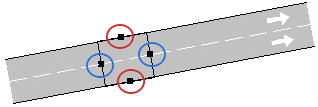
A detector can be located in any number of section lanes. When created, it occupies all the lanes in the section. To change the lanes it covers, select it, click on any of the two lateral points (red points in the figure below) and drag the point to adapt the detector to the desired lanes. Note that if a detector is moved to a section with more lanes, it will keep the same number of lanes it started with and must be expanded to cover all the lanes in the new section.
To change the length of a detector, select it, click on the front or back point (blue points in the figure) and drag the point to adjust the detector’s length to the desired one.
If all the detectors’ labels (ID and name) should be shown in a 2D View, select the Show Label option found in the context menu of the detector.
Detector Editor
The detector editor is used to name the editor and set its measuring capabilities.
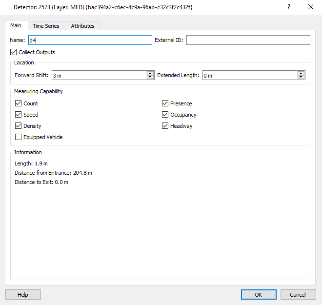
For more information about each capability refer to Detection Data Gathering.
If the Collect Outputs option is left unchecked, data for this detector will not be stored in the output database. This is used to reduce the database size. Select this option when detectors are used in actuated control but not involved in the calibration or validation process.
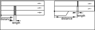
The Extended Length parameter extends the physical length of the detector to the distance specified. This can extend it into the following turn movement. The detector will gather information for vehicles in its physical length plus its extended length.
The Forward Shift parameter shifts both the physical start and end of the detector downstream by the distance specified. This can be used to locate a detector on a turn movement.
Detector Time Series
The Time Series tab appears after a simulation has been run. It has the same options and function as the Time Series tab in other objects and can display detector data graphically, in tables, and in comparison with date from a real data set or from a prior simulation. The table view also shows the values of the four Theil's U statistics; the association measure U, and the values of the measure for the bias (U~m~), variance (U~s~), and covariance (U~c~).
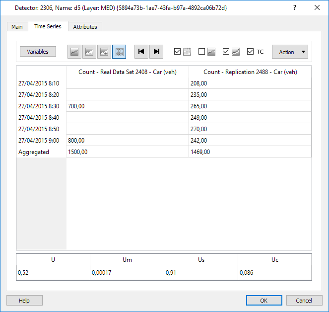
Further actions are available in the Detector Time Series tab if a real data set is available:
- Show GEH
- Copy Theil data to the system clipboard.
Detector Attributes
The Attributes tab provides the detector information. In a dynamics simulation , this includes the detection state as the simulation is run for the SI (Simulation Instantaneous) statistics such as the occupancy state or the speed of a vehicle currently over the detector.
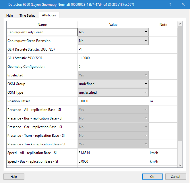
If the scenario specifies a Real Data Set, then the GEH statistic will be calculated for the detector at the end of the simulation when requested in the scenario validation tab.
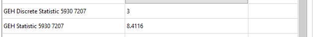
The GEH statistic quantifies the difference in simulated and observed flow. The GEH Discrete value classifies it and the action to be taken.