Pedestrian Simulator
When modeling pedestrians in microscopic simulations, Aimsun Next offers a choice of two main pedestrian simulators: the first is the embedded Aimsun Next pedestrian simulator. The second main option is Legion for Aimsun. The two simulators are complementary but best serve different types of project.
Note: One key difference between Aimsun Next's microscopic simulator and Legion for Aimsun is that, currently, focal points and focal segments (mentioned later in this topic in relation to exit centroids and decision nodes) only apply to Legion for Aimsun. Aimsun Next uses its own calculations to manage similar behavior.
Aimsun Next's embedded microscopic pedestrian simulator is particularly useful for mobility engineers: it is designed to model the movement of pedestrians on sidewalks, the interaction between pedestrians and traffic at crosswalks, and the boarding and alighting process at transit stops.
The focus is on ease of use, speed, multiplatform support, and deep integration with the Aimsun Next platform. The aim is to extend the mobility modeling workflow (for example, with the possibility of using Dynamic Transit Assignment to get skims for the four-step model).
Legion for Aimsun is particularly useful for pedestrian engineers working with OpenBuildings Station Designer and the Legion Simulator. It is designed to model the interaction between pedestrians and traffic around pedestrian facilities, ranging from stations to sports venues, and the activities of pedestrians inside those facilities, including the use of escalators, elevators, turnstiles, and vending machines, etc.
If you have previously used Legion for Aimsun Lite, Base, or Extra you might prefer to use our new in-house Aimsun Next pedestrian simulator because it supports everything that you could do before, but with no limit on the number of pedestrians. It also runs in Mac and Linux, it's faster, and it doesn't require a separate license.
Editing is also quicker because you no longer have to create obstacles around the road sections and buildings imported from OpenStreetMap. This is because pedestrians automatically recognize those objects as non-accessible space. And if you have models already built for Legion for Aimsun, the new pedestrian simulation can run them without further modifications.
The embedded Aimsun Next pedestrian simulator is a fully integrated plug-in for Aimsun Next microscopic simulations and is a powerful transport and pedestrian modeling application.
For mesoscopic simulations, we use a simpler embedded pedestrian simulator. Currently this simulator only works with Dynamic Transit Assignments.
It runs very fast computations of large amounts of pedestrians moving through the network for mesoscopic-level projects. To learn more about how we simulate pedestrians in mesoscopic simulations, see Mesoscopic Pedestrian Simulator.
The following subsections describe how to model pedestrian–traffic interaction. We indicate which aspects apply to microsimulations only.
- Pedestrian Types: How to create pedestrian types (micro and meso).
- Pedestrian Areas: Configuring the areas where pedestrians move (micro only).
- Pedestrian Crossings and Crosswalk Areas: Configuring the areas where pedestrians and vehicles interact (micro only).
- Signalized Pedestrian Crossings and Crosswalk Areas: Including a pedestrian crossing or a crosswalk area in a signal control plan (micro only).
- Pedestrian Centroids: Configuring pedestrian destinations (micro and meso).
- Routes and Demand: Setting the pedestrian demand and the routes taken (micro and meso).
- Transit: Describing how pedestrians board and alight from transit vehicles (micro and meso).
- Simulation: Running the simulation (micro and meso but handled differently).
- Outputs: Documents the outputs provided by the pedestrian simulator (micro and meso).
Pedestrian Types
A pedestrian type is a group of pedestrians with common characteristics used for modeling in the simulation environment. Pedestrian types are created to simulate how different parts of a target population will behave (and are visualized) in an Aimsun Next simulation.
Create New Pedestrian Types
Create a new pedestrian type by selecting Project > New > Pedestrians > Pedestrian Type.
A new pedestrian type will be created in the Pedestrian Types folder.

Change Pedestrian Type Settings
To edit a pedestrian type, double-click on it to open the pedestrian type editor.

The pedestrian parameters are divided between individual parameters and force parameters.
Individual parameters:
- Walking Speed: the desired walking speed of the pedestrian.
- Radius: determines the size of the pedestrian.
Force parameters are divided depending on whether the pedestrian is waiting to cross, walking, or running (when the pedestrian is crossing and the traffic light becomes red). They are also divided in the categories of Driving, Walking and Obstacle forces, depending on whether they are related to the pedestrian reaction to its own state, the pedestrian reaction to other pedestrians, or the pedestrian reaction to obstacles.
- Driving Force Relaxation: models the acceleration and aggressiveness. The shorter the relaxation time, the more pushy pedestrians will act.
- Interaction Strength: models how quickly the exerted force decreases with the distance.
- Interaction Range: models the influence of distance on the repulsive force.
- Anisotropy of Interaction: represents the effective field of view, which takes the form of a dimpled limaçon.
Note: The only parameter used in meso simulations is the Walking Speed.
Choose How Pedestrians Are Visualized
Use the 2D and 3D Shapes tabs on the Pedestrian Type Settings window to define how the pedestrians for this type are represented visually within Aimsun Next.

For 3D pedestrian shapes the percentage of different pedestrians to be generated within the group (e.g. the ratio of male, female and child pedestrians) can be adjusted.

The Always Vertical option ensures that objects keep their vertical aspect when moving on slopes. This should be ticked for pedestrians, so that they move realistically up and down stairs, for example.
Pedestrian Areas
Pedestrian areas are used to define spaces where pedestrians can move.
Define Where Pedestrians Can Go
To create a new pedestrian area, select the Pedestrian Area tool on the tool bar and draw the required polygon in the 2D view. This is the shape which defines a space as accessible to pedestrians. It should not overlap other pedestrian areas.

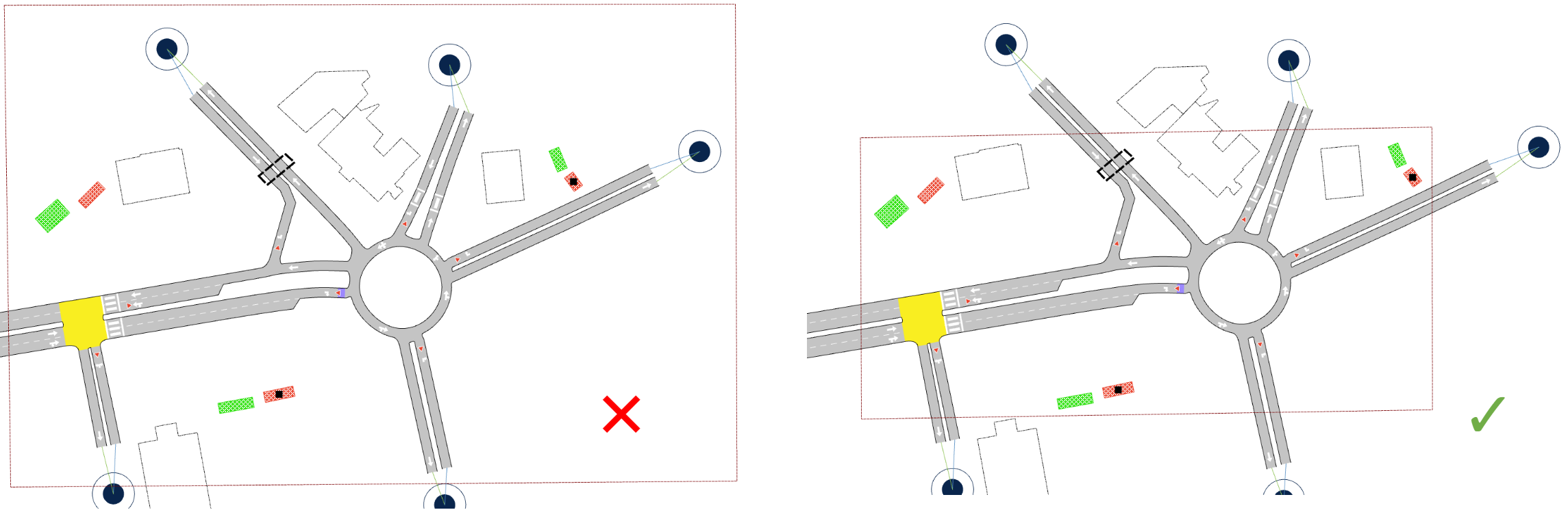
Note: As well as not overlapping other pedestrian areas, it is important that the area does not contain any gaps beyond and around the end of road sections. In the examples below, the area on the right meets this requirement correctly while the left-hand area contains such gaps.
Define Where Pedestrians Cannot Go
Pedestrian obstacles prevent pedestrians entering defined areas such as buildings, walls or even street furniture. Pedestrian obstacles are created inside the pedestrian area using the tools in the tool bar for polyline and polygon obstacles. Only the part of a pedestrian obstacle that is placed inside a pedestrian area will be considered.
In addition to user created obstacles, other objects will be automatically considered by pedestrians: sections, nodes, and all objects of type building (for example, OSM imported buildings).
Polyline Obstacles
Select the Polyline Obstacle tool and then click on the network as many times as needed to create the shape. Double-click to finish the obstacle. Parts of the polyline outside the pedestrian area geometry will be automatically discarded. An existing polyline can be used to generate a polyline obstacle with the Generate Pedestrian Obstacle option from its context menu.

Polygon Obstacles
Select the Polygon Obstacle tool and then click on the network as many times as needed to create the shape. Double-click to finish the obstacle. Parts of the polygon outside the pedestrian area geometry will be automatically discarded. An existing polygon can be used to generate a polygon obstacle with the Generate Pedestrian Obstacle option from its context menu.

Pedestrian Crossings
Pedestrian crossings, together with Crosswalk Areas, are the key areas where vehicles and people interact. These two type of objects are, within an Aimsun Next traffic network, where these interactions are simulated to determine how they will effect pedestrian and vehicle use of the traffic network.
Create a New Pedestrian Crossing for a Node
Use the Pedestrian Crossing tool to create a new pedestrian crossing. Select the tool on the tool bar and click to place the new crossing at the start or the end of a section. Pedestrian crossings can only be located at the start or the end of a section (or both) and nowhere else.

Change the Length of a Pedestrian Crossing
To change the length in the road section of a pedestrian crossing, first select the crossing, then click on the front or back point and drag it to alter the length.

Define Waiting Areas
For pedestrian crossings inside a pedestrian area, it is possible to specify the area where pedestrians will wait before they have the right to cross the section. Waiting areas are defined by default as a 4-vertex polygon at each side of the pedestrian crossings.
The whole area can be moved or it can be reshaped by moving any of the vertexes.

Pedestrian Crossing parameters
Waiting areas can be discarded in the pedestrian crossing properties.

Inside a pedestrian crossing, pedestrians have priority over vehicles. Safety Margin Front and Safety Margin Back define the safety distance inside the pedestrian crossing that vehicles need to assure to pedestrians going toward and away from the vehicle respectively.
The option to Consider as Yellow Box will avoid vehicles stopping and blocking the pedestrian crossing, independently of whether the node is a yellow box.
Crosswalk Areas
Crosswalk Areas are a generalization of pedestrian crossings with arbitrary geometry and that can be used by pedestrians to cross in nodes. Inside crosswalk areas, pedestrians have priority over vehicles.
In order to create a crosswalk area, first define a polygon. Next convert it to a crosswalk area by right-clicking on the polygon and selecting the option Convert To > Crosswalk Area.
Crosswalk Areas inside pedestrian areas will also allow editing the 4-vertex polygons at each side defining the waiting areas.

Signalized Pedestrian Crossings and Signalized Crosswalk Areas
Pedestrian crossings and crosswalk areas can also be included in signal controlled junctions using either fixed time signal or actuated signals triggered by pedestrian presence. First the crossing or crosswalk area must be included in a signal group in the node. If the controller is an actuated controller rather than fixed time, push buttons will automatically be considered to request for green as a pedestrian steps into the waiting area.
Signal Groups
To add a pedestrian crossing or a crosswalk area to a signal group, first select the signal, then toggle on the elements to be added to it using the Signal Group Editor. Note that a pedestrian crossing or a crosswalk area can only be associated with one signal group.

Pedestrian Behavior at Signalized Junctions
Pedestrian signals at crosswalks have three states: walk, flash (don't walk), and don't walk. Aimsun Next presents these states as green, yellow, red, respectively.
When the signal flashes, pedestrians who have not yet entered the crosswalk have the option to move quickly to cross the road or to stop and wait for the next green signal. Aimsun Next calculates and applies a percentage of pedestrians who will either enter the crosswalk or who will wait.
In action, this tends to mean that pedestrians will cross in the first or early part of the flashing signal period but will cease to cross in the second or later part of the flashing signal period.
To achieve this, Aimsun Next applies the same control plan settings of Yellow Time and Red Percentage that vehicles react to at signals. For more information, see Yellow Time.
Pedestrian Centroids
Pedestrian centroids are used as the origin and destination (OD) points for pedestrians in the model. These control the flow of pedestrians entering and exiting the network.
Create a Pedestrian Centroid Configuration
A pedestrian centroid configuration consists of a set of entrance and exit centroids and their related OD matrices and routes.
Pedestrian centroid configurations are independent of other centroid configurations, it is therefore possible to activate them at the same time as a vehicle centroid configuration.
The first time a pedestrian entrance or exit is created, a new pedestrian centroid configuration will also be created automatically (and will be set as activate), and the pedestrian entrance or exit will belong to it, as well as any others created while the pedestrian centroid configuration remains as Active.
To create a new pedestrian centroid configuration, select Project > New Pedestrians > Pedestrian Centroid Configuration.
Pedestrian Entrance Centroids
A pedestrian entrance centroid is the area where pedestrians are generated and enter the network. To create a new entrance centroid, select the Create a Pedestrian Entrance tool on the Tools Toolbar and click on a point inside a pedestrian area and click a second time to create an entrance with a rectangular shape within those two points.

A green box will appear, which represents the entrance centroid.

The size of an entrance centroid can be modified by dragging any of the rectangle points that appear when selected. There is a minimum size of 3 meters (height) and 1 meter (width).
Pedestrian Exit Centroids
A pedestrian exit centroid is the area where pedestrians exit the network. To create a new exit centroid select the Create a Pedestrian Exit tool on the Tools Toolbar and click on a point inside a pedestrian area and click a second time to create an exit with rectangular shape within those two points. This will create a red box to represent the exit centroid.


The size of an exit centroid can be modified by dragging any of the rectangle points that appear when selected. There is a minimum size of 3 meters (height) and 1 meter (width).
When using Legion for Aimsun, it is also possible to define the way that pedestrians approach the centroid by dragging and moving its central focal point (this is the default option) or dragging the focal point onto a side of the centroid to create a focal segment. See Decision Nodes for detailed information about focal points and focal segments.
Routes and Demand
Routes are used to determine the path of pedestrians from their entrance into the network to their exit. They define how pedestrians approach critical points (defined as decision nodes) and set demand through particular routes to simulate how the volume of people can impact traffic flow.
Pedestrian OD Routes
A pedestrian origin-destination (OD) route is a pre-determined path between an entrance and exit centroid that pedestrians will follow. There are several elements which make up a pedestrian OD route.
Route Elements
A pedestrian OD route is likely to have intermediate targets, or sections in an OD route, between entrance and exit. For example, these might include pedestrian crossings, decision nodes, service points, or level changes.
These must be set in the correct order, and the list of pedestrian crossings and level changes must be complete so that the route is fully determined for pedestrians to use.
Note: Because mesoscopic pedestrians are only used in dynamic transit assignments, they don't require user-defined custom routes. The Route Elements section applies only to microscopic simulations.
Pedestrian Crossings and Crosswalk Areas
Pedestrian crossings and crosswalk areas are locations where vehicles and pedestrians conflict. To simulate this interaction with pedestrians (either signalized or not) through a particular site in an intersection, add a pedestrian crossing or a crosswalk area to the route.
Decision Nodes
Decision nodes are virtual areas which pedestrians pass through as they travel on their route. They are useful for defining realistic pedestrian paths and movements. To create a decision node, click the Create a Decision Node tool in the Tools toolbar, click in the 2D view and drag its vertices to define the shape of the decision node.


The way in which pedestrians walk toward the decision node can be adjusted using focal points or focal segments (currently in Legion for Aimsun only). Instead of focal points and segments, the Aimsun Next pedestrian simulator uses a geometric calculation to manage how pedestrians walk toward the decision node. No further intervention is required.
- Focal Point (Legion for Aimsun) This is the default option; pedestrians walk toward the central (focal) point of the decision node. To adjust the direction of pedestrians, you can click and drag the focal point to different positions inside the area of the decision node.

- Focal segment (Legion for Aimsun) You can change a focal point to a focal segment by dragging the focal point outside the outline of the decision node. When it reaches a side of the node, the point will change to a segment: the whole side of the exit segment will be highlighted to show that it will now function as a focal segment. Pedestrians will cross this segment as they enter the decision node.
The segment spreads the area in which pedestrians approach and enter the decision node; otherwise, they will approach in a straight line. The entrance angle is calculated based on the opposite segment, in the image, pedestrians will try to enter the decision node following the orange arrow.

Service Points
Service points are areas where pedestrians can wait for a while and then continue on their path. You can use them to model information boards, ATMs, and shops, etc. To create a service point, click the Create a Service Point tool in the Tools toolbar, click in the 2D view and drag its vertices to define the shape of the service point.

Service points have two different areas: an outer area and an inner area. The outer area is unshaded and defines the zone in which pedestrians will be redirected to the inner shaded area where they will receive the service. You can change the relative size of these areas by dragging the middle vertex of the service point. You can also move or rotate the service point area as required.

Double-click the service point to open the Pedestrian Service Point dialog.

The following parameters can be set.
- Pedestrians to Affect: Percentage of pedestrians crossing over the outer area of the service point that will be kept waiting.
- Capacity: Number of pedestrians that can be serviced at the same time.
- Aggressiveness: Defines the behavior of pedestrians when moving toward their waiting position:
- Low: Pedestrians will stop as soon as they can. They will not try to reach their waiting position unless there is no one else between them and their destination
- Medium: Pedestrians will try to reach their waiting position if there aren’t too many other pedestrians between them and their destination
- High: Pedestrians will try to reach their waiting position even if the service point is fully occupied.
- Queue Pedestrians: Tick this option to create a queue before entering the inner waiting area of the service point.
- Queue Orientation: Tick this option to define the angle of the queue in relation to the service point (e.g. 45° or 90°).
- Delay Time: Select one of three different kinds of delay:
- Fixed: Pedestrians will wait for a fixed time
- Wait Until: Pedestrians will wait until a certain time
- Variable: Pedestrians will wait for a variable time, defined with a Mean Time and Deviation (both in seconds).
- Distribution: Tick this option to define how pedestrians are distributed at the service point. You can choose one of four options for placing the distribution points that pedestrians will aim for:
- Top
- Middle
- Bottom
- Whole Area – will distribute points across the whole of the shaded zone.
- Number of points: The number of distribution points that will be generated. This depends on the size and nature of the service point.
Level Change Objects
A Level Change Object represents either a footbridge or an underpass that pedestrians use to cross a road not influencing the normal traffic behavior.
To create a new Level Change Object, click the level change button highlighted in the screen shot below.

Double click on it and the following dialog appears.

The editor is used to define the entrance and exit stairs by setting the side (Access A, B, C or D), the width and the use percentage, which is applied when there is more than one stair at the same side.
The Height parameter defines whether the object represents a footbridge or an underpass and its elevation change.
Creating a Pedestrian OD Route
To create a new pedestrian OD route between entrance and exit centroids, right-click over the pedestrian centroid configuration and select the Pedestrian OD Route option from the contextual menu.

Next, double-click on the new Pedestrian OD Route and the Pedestrian Route Editor window will open.
The OD route settings are edited by clicking on an item in the 2D window to add new route items (any of the elements detailed here). The Delete button removes selected items and the Up and Down buttons move selected items in the list to change the route order.
Finally, select the entrance (Origin) and exit (Destination) centroids for the beginning and end of the route.

Define Pedestrian Trips with a Pedestrian OD Matrix
Pedestrian trips between the origin and destination are defined using a pedestrian OD matrix. This applies to both microscopic and mesoscopic pedestrians.
To create a pedestrian OD matrix, right-click over a pedestrian centroid configuration and select the Pedestrian OD Matrix option from the context menu

The matrix settings are entered in the Pedestrian OD Matrix Editor window. Pedestrian OD matrices have the same elements as Vehicle OD matrices. The only difference is the Pedestrian Type field, whose drop-down list enables you to select different pedestrian types for each matrix in the model.

Route percentages can be assigned for the origin/destination pair (up to 100%). If the total percentage is less than 100, the remaining pedestrians will follow the shortest path between centroids.

Transit
You can specify the behavior of pedestrians approaching transit in one of two ways:
- Define the pedestrians arriving at each transit stop and boarding (disappearing from the model) and alighting (entering the model). This applies to micro pedestrians only.
- Let the pedestrians choose whether to use transit at all, and which transit lines (the pedestrian agent exists from the beginning to the end of the trip), by activating the Dynamic Transit Assignment in the simulation's experiment dialog.
Dynamic Transit Assignment
Pedestrians have the option to take transit to reach their destination, as long as the transit system information is available and the model is activated in the simulation experiment. This option is located in the experiment Behavior tab, inside the Pedestrians group box. Here you can activate the Dynamic Transit Assignment and set whether a flat fare has to be considered and with which cost, and also the transfer penalty function.
Note: The fare in a Dynamic Transit Assignment includes Flat Fare if set as such in the experiment, and Boarding Function cost if a boarding function is selected in the Transit Stop dialog.
Pedestrians will choose, comparing the path costs when using transit or walking only, whether to board a transit vehicle or not. When the Dynamic Transit Assignment is considered, pedestrian OD routes will be ignored.
Routes are calculated by looking for the shortest path. Transfers within a stop are considered, and transfers between different stops are considered, but only if pedestrians can walk from one stop to the other stop, according to their waking model (only micro pedestrians use pedestrian areas).
In microsimulations, if a pedestrian is waiting for a transit vehicle which has no spare capacity at the transit stop, the pedestrian will recalculate its route to its destination from here. In simpler mesosimulations there is no concept of rerouting, so the pedestrian will wait until the next transit vehicle of the same line arrives.

The total cost of a trip that includes transit is calculated by adding each one of the cost components multiplied by a weight. These weights can differ per pedestrian type and in fact they are defined per user class, which also includes the trip purpose.

The choice between a pedestrian walking the whole journey and using transit takes into account a pre-calculation of the transit trip cost that presumes that transit vehicles will be dwelling at a particular transit stop at the time it takes from their departure to reach that transit stop in free-flow time + pre-defined dwell times according to the line's timetable info for the previous stops.
Transit Stops
Parameters
Double-clicking on a transit stop opens its dialog. The Pedestrians tab contains parameters related to simulating pedestrians and simulation dwell times for transit vehicles.

The following attributes can be defined:
- Wait For Pedestrians To Board: When checked, stopped transit vehicles will wait until a pedestrian arrives at the stop. This allows the simulation of taxi ranks. This applies to micro pedestrians only.
- Boarding Time: Time spent by each pedestrian that boards a transit vehicle. Used to calculate the vehicle stop time.
- Alighting Time: Time spent by each pedestrian that alights from a transit vehicle. Used to calculate the vehicle stop time.
Note: In mesoscopic simulations, these boarding and alighting times are used to compute the vehicle's total stop time, alongside the number of doors and door type for each transit vehicle. For more information about transit vehicle doors, see Vehicle Types.
Entrance and Exits
Entrance and Exits are only considered in microscopic simulations when not using the Dynamic Transit Assignment.
Right click on a transit stop to create either an entrance or an exit. Note that a stop can only have one of each kind of centroid. The option will only work on those stops that are inside a Pedestrian Area.


Centroids are placed taking into account the section direction: entrance centroids are placed at the end of the stop and exit centroids at beginning.
Centroids linked to transit stops are “virtual” centroids, the aim of this kind of centroid is to allow trips, routes, etc. to be defined. When a simulation is running, the centroid geometry changes according to the current transit vehicle position at the stop so that pedestrians will board or alight realistically.
Exit Waiting Areas
When the transit stop is connected to a pedestrian exit centroid, the area where pedestrians will wait until they board a transit vehicle can be defined.

Transit Lines Data
The information needed for transit lines is the standard: routes and timetables.
In addition, in a microscopic simulation, when not using the Dynamic Transit Assignment, you can define how many passengers will board and alight at each stop in the line by selecting each schedule and toggling on the Show Pedestrian Info checkbox and fill in the corresponding data.

Initial Passenger Load and Deviation define the number of pedestrians present inside a bus when it starts its route. The value is calculated using a Normal distribution with minimum and maximum values (0 and maximum vehicle capacity respectively).
The Alighting Mean and Deviation define the number of people to generate when a transit vehicle stops at the stop. The value is calculated using a Uniform distribution. The number of pedestrians that will alight the bus also depends on the number of pedestrians inside the transit vehicle.
Boarding Mean and Deviation define the number of people that will take a transit vehicle stopped at the transit stop. The value is calculated using a Uniform distribution. The total number of pedestrians that will board the transit vehicle depends on how many pedestrians are waiting at the stop when the vehicle arrives.
Independently on whether the dynamic transit assignment is active or not, once the vehicle stops, its stop time is recalculated using the number of pedestrians that will alight and board. If the mean stop time is 0, the real stop time will be the amount of time that pedestrians take to alight and board the transit vehicle. Otherwise (mean stop time > 0), the vehicle will remain at the stop for at least the time defined in mean stop time field.
Vehicle Attributes
Transit vehicles have a parameter to define the maximum number of pedestrians that can board. The value can be set either as a multiplying factor of vehicle length or as a total value.

On the Dynamic Models > Articulated and Doors subtab, you can specify whether the vehicle is articulated and also define the number of doors, their type, and their distance from the front of the vehicle.
The available types of door are:
- Vehicle Entrance: only boarding is allowed.
- Vehicle Exit: only alighting is allowed.
- Entrance and Exit: boarding and alighting are allowed.

In microsimulations, the number of pedestrians who board or alight is distributed equally between all exit/entrance doors.
In mesosimulations, alighting is distributed equally across all exit doors, while the boarding distribution depends on both the existence of non-exit doors and the flow of alighting pedestrians. Further details can be found in the boarding and alighting logic section of the Mesoscopic Pedestrian Simulator.
OD Matrix editing
Exit centroids linked to any transit stop will appear in the Trips table where the amount of people moving toward the stop can be defined.

Entrance centroids linked to any transit stop will appear in the Percentages table to define the pedestrian destination percentage. This percentage must sum to 100. The number of pedestrians that will alight from a bus is defined in the transit line timetable.
OD Route editing
As for normal entrance centroids, routes starting in a transit stop can be defined by selecting the linked entrance centroid as the OD route origin centroid.
Simulation
Add Pedestrians to Traffic Demand
Add pedestrian OD matrices to traffic demand as for a vehicle OD matrix using the Traffic Demand Editor window. These can be combined with matrices from other centroid configurations by clicking on the Add Demand Item button for the current configuration.

Edit Scenario Settings
Select the traffic demand containing pedestrian matrices in the Main tab of the Scenario Editor.
Pedestrian Simulator Outputs
Pedestrian simulator outputs are generated by ticking the Sections, Crossings and Crosswalk Areas, Transit Stops, and Service Points options in the Dynamic Scenario editor > Outputs to Generate > Statistics tab.

Replication Outputs
Note: Currently there are no outputs from mesoscopic replications. The following apply to microscopic simulations only.
For each pedestrian type and for the aggregated value for all pedestrian types (grouped under Pedestrian - All), the following Time Series will be linked to the simulated replication, and their corresponding global value found in the Outputs Summary:
- Pedestrian Flow: Number of pedestrians in the network by hour.
- Pedestrian Harmonic Speed: Harmonic Speed of pedestrians (in km/h or mph).
- Pedestrian Maximum Stop Time: Maximum time that a pedestrian is stopped (in seconds).
- Pedestrian Number of Stops: Mean of number of stops.
- Pedestrian Speed: Mean Speed of pedestrians (in km/h or mph).
- Pedestrian Stop Time: Calculated time when pedestrian are stopped for any reason (in seconds).
- Pedestrian Total Distance Traveled: The sum of all pedestrian distance traveled (in km).
- Pedestrian Total Travel Time: The sum of all pedestrian travel time (in seconds).
- Pedestrian Travel Time: Time that pedestrians take to reach their destinations (in seconds).
- Pedestrian Waiting Time at Transit Stop: The sum of all pedestrian waiting time at a transit stop.
- Pedestrian Walking Time: Calculated time when pedestrians keep moving (in seconds).
- Pedestrians Inside: Number of pedestrians that have entered the network.
- Pedestrians Outside: Number of pedestrians that have exited the network.
Pedestrian Crossings Outputs
Note: These outputs apply to microscopic simulations only.
For each pedestrian type and for the aggregated value for all pedestrian types (grouped under Pedestrian - All), the following Time Series will be linked to the Pedestrian Crossing on simulated sections:
- Pedestrian Count: Number of pedestrians in the network that cross the pedestrian crossing.
- Pedestrian Walking Time: Mean calculated time it takes pedestrians to cross the influence area (entering the waiting area) and the pedestrian crossing (in seconds), not including the time the pedestrian might have been waiting. This is shown by the highlighted red area below:

- Pedestrian Effective Walking Time: Mean calculated time that pedestrians take to cross the Pedestrian Crossing (in seconds). Shown in the highlighted green area below:

- Pedestrian Waiting Time: Mean calculated time pedestrians are waiting at the Pedestrian Crossing (in seconds) for the pedestrian traffic light to become green.
OD Pair Outputs
Note: Currently there are no outputs from mesoscopic replications. The following apply to microscopic simulations only.
For each pedestrian type and the aggregated value for all pedestrian types (grouped under Pedestrian - All) and each selected OD pair, the following Time Series will be linked to the simulated Traffic Demand:
- Pedestrian Harmonic Speed: Harmonic Speed of pedestrians (in km/h or mph). Each interval value will be calculated considering the pedestrians that reached their destination in the specified interval.
- Pedestrian Maximum Stop Time: Maximum time that a single pedestrian has been stopped (in seconds) in the specified interval.
- Pedestrian Number of Stops: Mean number of stops. Each interval value will be calculated considering the pedestrians that reached their destination in the specified interval.
- Pedestrian Speed: Mean Speed of pedestrians (in km/h or mph). Each interval value will be calculated considering the pedestrians that reached their destination in the specified interval.
- Pedestrian Stop Time: Mean time considering for how long pedestrians remain stopped for any reason (in seconds). Each interval value will be calculated considering the pedestrians that reached their destination in the specified interval.
- Pedestrian Travel Time: Mean Travel Time that pedestrians take to reach their destinations (in seconds). Each interval value will be calculated considering the pedestrians that reached their destination in the specified interval.
- Pedestrian Walking Time: Mean time of the pedestrians moving time (in seconds). Each interval value will be calculated considering the pedestrians that reached their destination in the specified interval.
- Pedestrians Inside: Number of pedestrians that have entered the network.
- Pedestrians Outside: Number of pedestrians that have exited the network.
Service Point Outputs
Note: These outputs apply to microscopic simulations only.
For each pedestrian type, and the aggregated value for all pedestrian types (grouped under Pedestrian: All), the following time series will be linked to the simulated service points:
- Attracted People: Number of pedestrians that detoured to visit the service point.
- Crossing People: Number of pedestrians that have crossed the service point area.
- Served People: Number of pedestrians served at the service point.
- Waiting Time: Mean pedestrian waiting time at the service point.
Transit Stop Outputs
Note: Currently there are no outputs from mesoscopic replications. The following apply to microscopic simulations only.
For each pedestrian type and the aggregated value for all pedestrian types (grouped under Pedestrian – All), the following Time Series will be linked to the simulated transit stops:
- Pedestrian Alighting: Number of pedestrians that get off from the transit vehicles at the Stop.
- Pedestrian Boarding: Number of pedestrians that get on the transit vehicles at the Stop.
- Pedestrian Total Waiting Time at Transit Stop: Sum of all pedestrian waiting time at the stop.
Transit Vehicle Outputs
Note: These outputs apply to microscopic simulations only.
The outputs of transit vehicles, available during an animated simulation by double-clicking on the simulated vehicle, are:
- Static Attributes tab: Maximum Number of Passengers
- Dynamic Attributes tab: Number of Passengers

Additional Pedestrian Simulator Outputs for Dynamic Transit Assignment
If you're running the Dynamic Transit Assignment, there are additional outputs that can be generated.
Skim Matrices
In order to obtain skim matrices with costs per OD pair, activate the skims generation at the replication, Outputs to Generate tab.

The following skims will be provided:
- Total Cost: weighted sum of all cost components.
- In-Vehicle Time
- Fare
- Transfer Penalty
- Total Waiting Time: waiting time at first access and transfers.
- Walking Distance
Pedestrian Agent Outputs
Note: These outputs apply to microscopic simulations only because mesoscopic simulations don't include animated agents.
The main output for a pedestrian, available during an animated simulation with dynamic transit assignment, is the decomposition in segments of the trip. It can be accessed by double-clicking on the simulated pedestrian, and checking the Trip tab.

Dynamic Transit Trips
The Dynamic Transit Trips tab contains the data related to the paths that have been chosen by pedestrians (in a similar way to the Path Assignment tab for simulation vehicles). There is an optional filter for origin, destination and user class. When double-clicking on one of the trips, the detail of the segments will appear in a new pop-up window. Statistics as the number of pedestrians generated and arrived for each trip during the simulation, the expected cost, and experienced cost, as well as other components of a transit trip, will be shown in a table.

This information can be stored in a DPT file according to the settings in the Outputs to Generate tab in the replication.