Network Backgrounds
Images and vector drawings can be imported into an Aimsun document as blueprints to create the network. The accepted formats are:
- Vector formats: CAD files in DXF, DWG, DGN formats, and GIS files in Shapefile format.
- Raster Images, manual geolocation: JPEG, GIF, PNG, BMP.
- Raster Images, automatic geolocation: JPEG 2000, ECW, MrSID.
Normally any file to be used as a background will be available in one of these formats or can be converted to one of them.
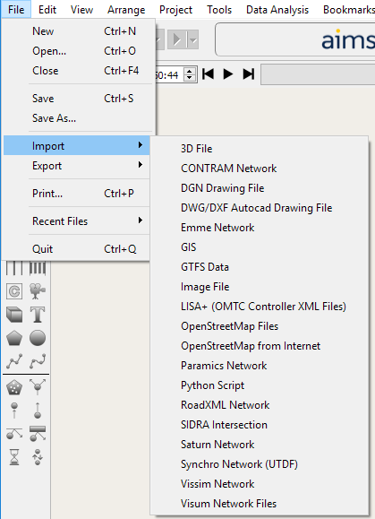
Background Import is available from the "New Project dialog, or from the File menu, Import* option.
CAD Files
Importing
Import a background into an open model using the Import command from the File menu. Depending on the file type, a second dialog will ask for additional information.
Note that the imported file will not be stored in the Aimsun document, only the location of the file will be saved by default minimizing the database size. If the file or the model is subsequently moved then Aimsun Next will first search for the file in the model folder, then if the file is not found, request a new link to the file when the model is opened.
External background data can loaded as the model is opened or loading can be deferred. The data can be also be loaded and unloaded manually. Refer to the Layers window for a description of background retrieval.
CAD files, such as DWG, DXF or DGN files, are imported in a layer with the same name as the imported file with each CAD layer is imported as a sublayer. The CAD objects cannot be translated or scaled. The user can hide any individual layer and change how the content of each layer is drawn using the Layers window.
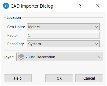
Individual objects in a CAD file can neither be edited nor selected. When importing a CAD file, the dialog below will be shown. The geo units in which the CAD file is coded: meters, feet or user-defined, must be specified plus the type of text encoding of the CAD file. User defined units let the user supply a multiplication factor used to scale the coordinates. If System encoding is chosen, the settings of the Operating System will be used.
GIS Files
These will be placed, as CAD files, in their own layer. Objects imported from a GIS file, unlike CAD files, can be selected and an information window displayed with a double click on the object.
For more information about importing GIS files, see GIS Importer/Exporter.
Image Files
Importing
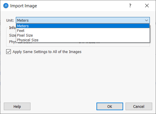
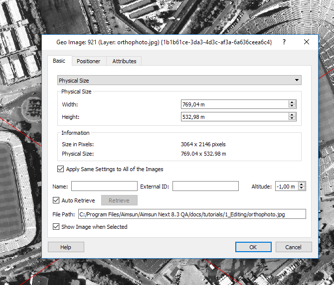
Import an image file with the import dialog. Depending on the option chosen, the import will scale the image by:
- Importing the image with 1:1 correspondence between pixel size and either feet or meters.
- Importing the image with a set size for each pixel.
- Importing the image with a set size for the image file.
Each image will be placed in a sublayer of the Images layer as a graphical object. An image can then be selected, translated, and scaled.
Placement and Scale
Some formats already include information about their position, scale, and rotation (DXF, DWG, DGN, Shapefiles, JPEG 2000, ECW, and MrSID). They will be placed at the correct position automatically.
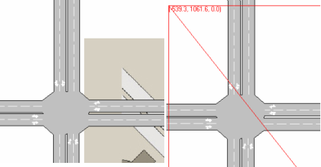
Other formats (JPEG, GIF, PNG and BMP) must be translated to the desired location and scaled to their correct size in meters or feet.
If object editing is not enable for the image layer, it will not be possible to select an image to move it or scale it. See the Layers Window for more information.
Placement
Select the image by clicking on it and use the mouse to drag it to its final position. When selected, the image will not be shown; only its position will be indicated. To make the image visible while selected, double click on it to show its editor and check the option Show contents while selected. Note that images from CAD files cannot be moved.
Scale
An image scale can be modified using its properties editor. Two scaling methods are available: one to set the size of the image, another to set the size of each pixel.
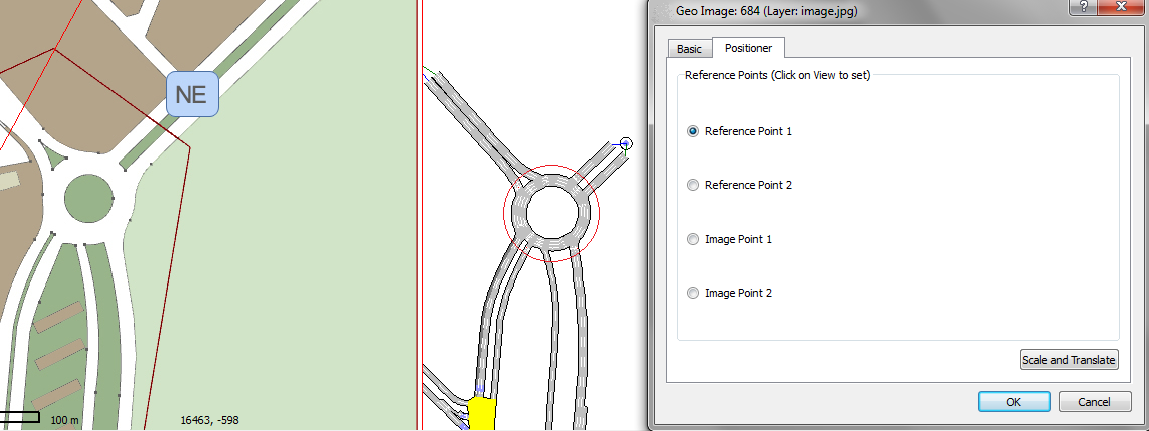
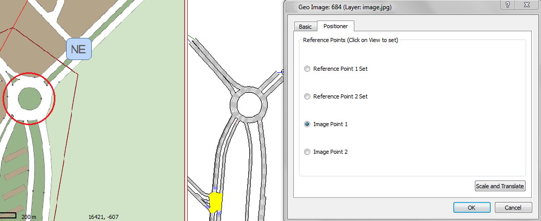
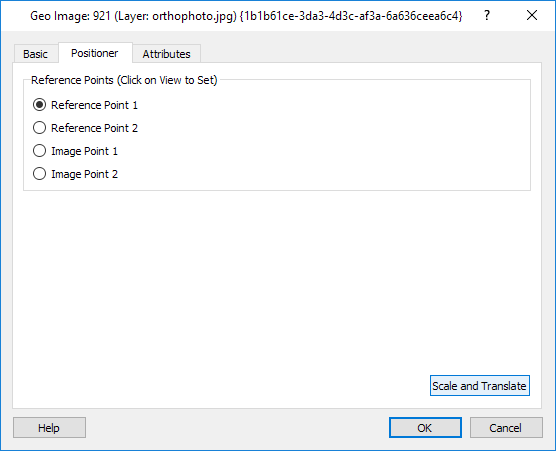
Using the Positioner tab
An alternative method to place and scale the image is to use the Positioner tab folder in the image editor. This allows the image to be placed at the desired location and at the desired scale by specifying two corresponding points on both the layer (usually against the underlying CAD file) and the image.
First, select Reference Point 1, in this case the center of a roundabout, by clicking in the view
Then select the second reference point (the roundabout to the south).
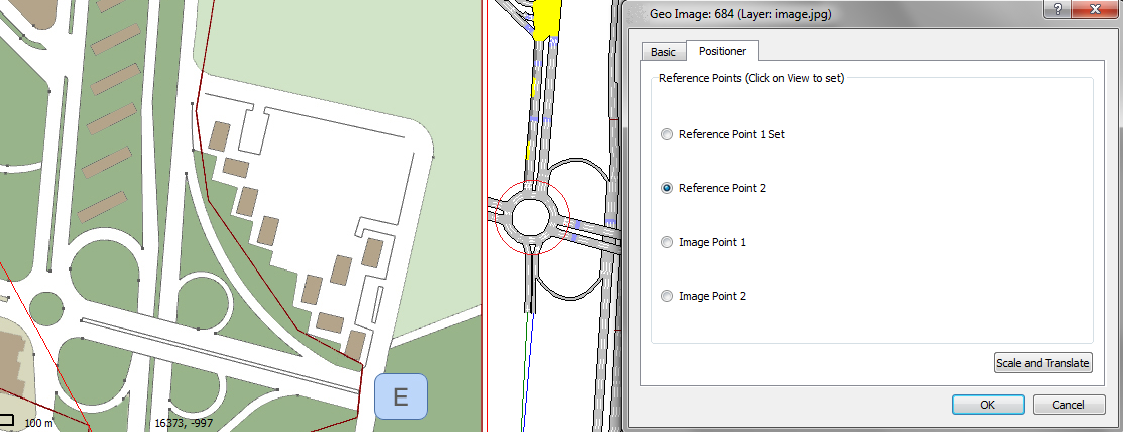
Then select the corresponding points on the image.
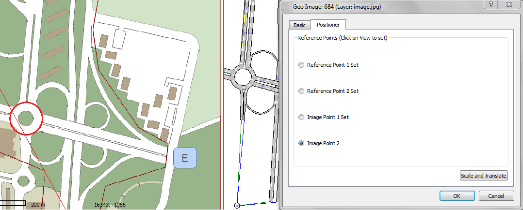
With all points set, clicking Scale and Translate positions and scales the image according to the chosen points.
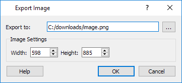
Exporting
To export an image of the current network view, click the Image option in the Export Menu and specify the image size (default is the window size) and the file to save.