Geometry Configuration Editing
Geometry Configurations are used by static and dynamic scenarios to create an alternative view of a traffic network. For example, they could be used to code a possible new commercial center, including new access and modifications to the surroundings, and to test two different scenarios: one with and another without that commercial center.
They are implemented as a list of objects that are only present and a list of objects that are not present when a particular configuration is active.
A configuration is active when it is assigned to a scenario and one of its experiments is active in the current view. When running an experiment, Aimsun Next will create a new traffic network to pass to the executor model (micro, meso, hybrid, macro ...) using only the relevant, present geometry.
Note: In such cases, objects are not really deleted from an Aimsun document, they are just not considered during simulations, assignments, and adjustments, etc.
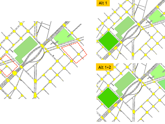
One scenario can have more than one geometry configuration active at the same time. This allows you to test combinations of individual modifications. For example, given this list of possible options:
- a new commercial center with a new local road layout
- changes in a corridor approaching the new center
- changes in a busy junction adjacent to the new center
you can create several scenarios:
- base scenario without the commercial center or any other changes
- another scenario with the commercial center and no changes
- another with the commercial center and the corridor changes
- another with the commercial center and the junction changes
- finally, a scenario with the commercial center and both corridor and junction changes.
You can then study the impact of the new center and the benefits of the proposed infrastructure changes.
Geometry configurations are provided by Aimsun Next in order to keep all the data in one document and to provide a mechanism to include them in scenarios according to the options being tested.
Creating a new Geometry Configuration
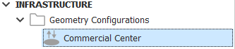
Geometry configurations are filed in the Infrastructure folder of the Project window.
To create a new geometry configuration, select Project > New > Infrastructure > Geometry Configuration.
In the Project window, you can also right-click Infrastructure > New > Geometry Configuration.
Geometry Configuration Editor
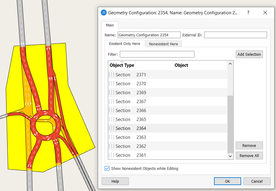
The Main tab has two subtabs: one lists objects that are Existent Only Here in the geometry configuration (being the new objects to be added to the base configuration); the other lists objects that are Nonexistent Here in the geometry configuration (being the base objects that will be replaced).
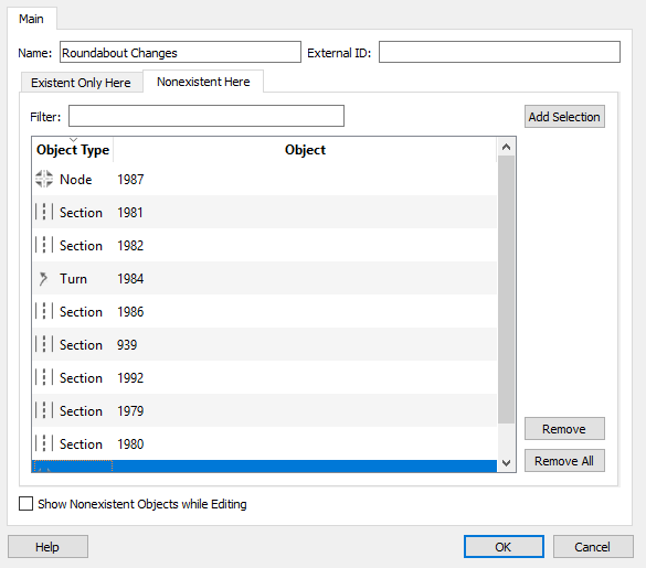
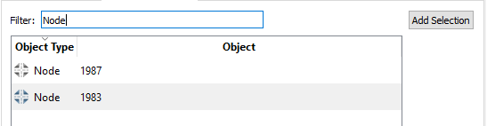
Use the Filter field to reduce the number of objects displayed by Object Type.
Click on any graphical object in the 2D view add it to the list of objects on the active subtab.
Click on an object that is already in the list to remove it.
To see both types of object in the 2D view, tick the box labeled Show Nonexistent Objects while Editing. Existent-only-here objects will be marked in red, nonexistent-here objects will be marked in orange (using this color ramp).
When editing a geometry configuration, make sure you select the relevant experiment in the 2D view so that you can see the visual impact of the configuration. For an experiment to be relevant, you must select the geometry configuration on the Main tab of its parent scenario dialog.
You might have more than one geometry configuration, so select as many configurations as you need to make them active for experiments.
Note on using Geometry Configurations with Centroid Connections
If the sections changed in a Geometry Configuration are connected to a Centroid, then the allocation of the vehicle arrivals to the sections must be set to cater for all Geometry Configurations. Consult the Centroid Editor for advice.
Using Transit Route Change Actions with Geometry Configurations
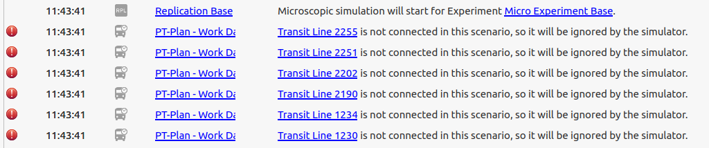
Sometimes a geometry configuration might interrupt or 'break' an established transit line in the base network. When running an experiment using the new configuration, this will generate warnings in the Log window.
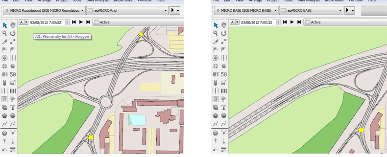
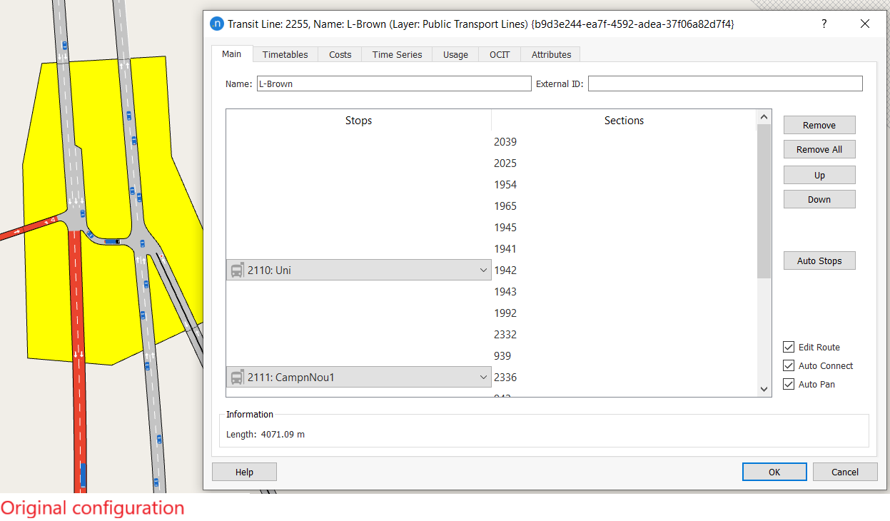
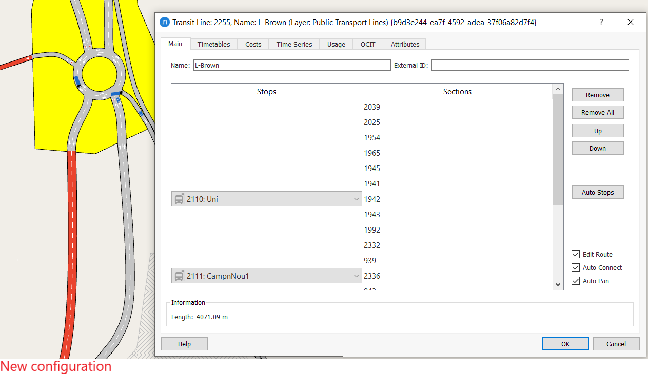
Let's take Transit Line 2255 as an example. In the screenshots below, the transit line in the original configuration is interrupted by the new roundabout.
If you run the experiment with the new configuration, warnings are generated for Transit Line 2255 (and other lines if they are also affected).
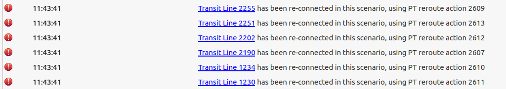
In these cases, the transit lines are ignored. However, if the model contains a transit route change action that 'repairs' the interrupted line, the simulator will use the action to correct the line and include it in the simulation. Again, the Log window will display the details:
In this case, Transit Route Change 2609 fixes the interrupted line, as pictured below.
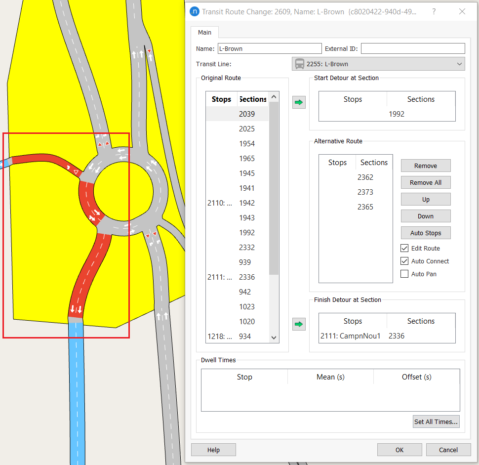
For instructions on how to create a transit route change action, see Transit Route Change.