Subnetwork Editing
A Subnetwork is a subarea of the global network that can be analyzed independently.
Once the network geometry for the area that is to be analyzed (without taking into account the rest of the network) has been created, the Subnetwork can be defined. To do this, first create a polygon that encloses the area. Refer to the Polygon Graphical Editing section for details on creating a polygon.
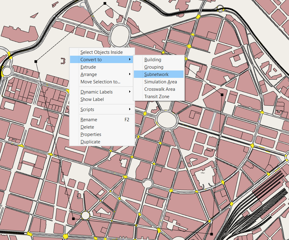
Once the polygon has been created, it can be converted to a Subnetwork by right clicking on the polygon to open its context menu and selecting Convert To : Subnetwork, as shown below.
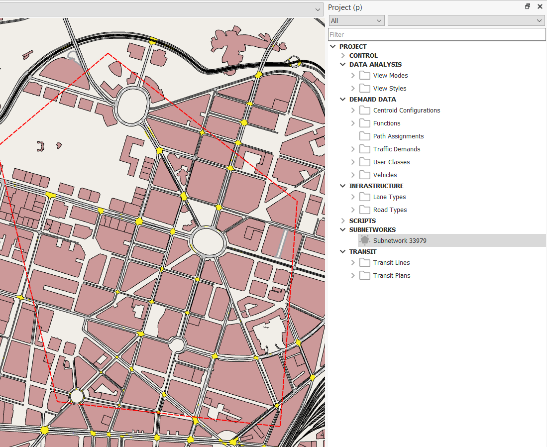
The polygon shape will change to a red discontinuous line defining the border of the Subnetwork and a new Subnetwork will be added to the Project Window's Subnetworks folder, as shown below.
Subnetwork Editor
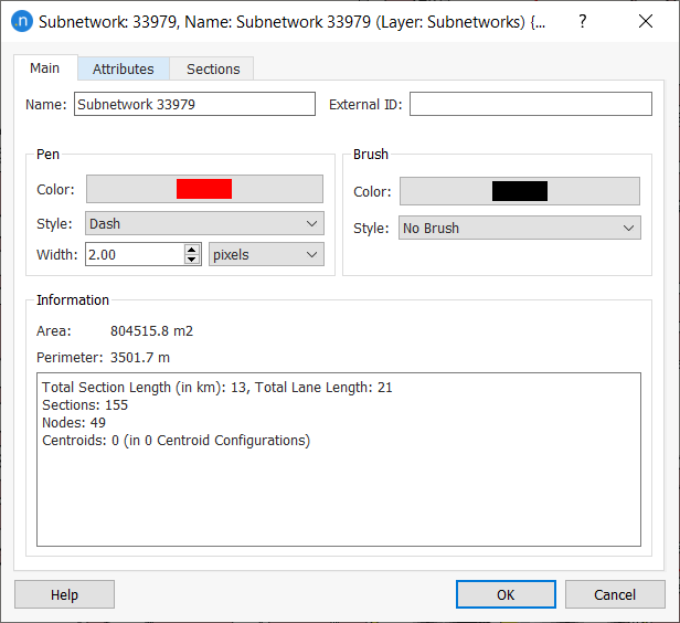
The Subnetwork editor can be accessed either by double clicking on the Subnetwork in the Project window or by double clicking on the Subnetwork polygon (provided that the Subnetwork layer allows editing, otherwise the Subnetwork polygon will not be selectable). The appearance of the polygon can be changed in the Subnetwork editor, exactly as with regular polygons.
Polygon Definition
If no information is entered in Sections tab (that is, the default state), the part of the network within the polygon lines will belong to the Subnetwork. A node is considered to belong to the Subnetwork if at least one of its turns is completely inside the polygon. A section belongs to the Subnetwork if the initial or ending point in its central line is inside the polygon or if any of its origin or destination nodes belongs to the Subnetwork.
Section Definition
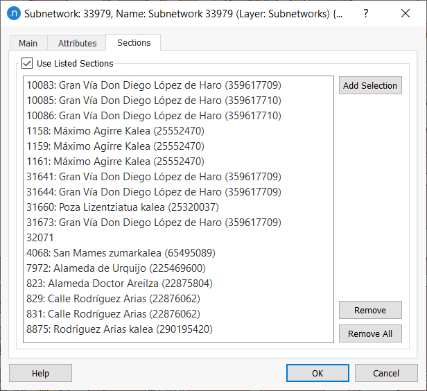
Alternately, a Subnetwork can also be defined by selecting of a set of sections (for example, the highway part of a network).
The list of sections must be specified in the Sections folder. Sections are selected directly in the view and, by pressing the Add Selection button, they will be added to the list. In this case, the Subnetwork contains all the sections listed, plus all the nodes with any of its turns connecting sections in the list, plus the sections connected to the nodes belonging to the Subnetwork. For example, if all the sections of road type highway are listed, the Subnetwork will contain the highways as well as the on- and off-ramps.
Subnetwork Layers
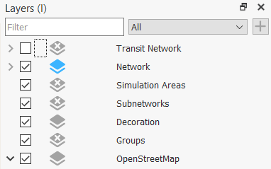
When creating the first Subnetwork a new layer will be created named Subnetworks into which all Subnetwork polygons will be added, as shown in the following figure.
If the existing Subnetwork borders need to be protected from editing the corresponding layer parameter Allow Object Editing will need to be unchecked. By default, the Subnetworks will be editable. In order to access the context menu of the Subnetwork, to access its editor by selection of the Subnetwork on the 2D View, or to add/remove/modify its vertices, this parameter must be checked.
In 2D views, when no filter is selected the whole network is drawn. If only a Subnetwork must be drawn in a 2D view, select it in the Filters option from the View context menu.
Context Editor
Objects can be generated within a Subnetwork using the context menu.
A Subnetwork has similar capabilities to the full project network. A Subnetwork can contain a Centroid Configuration specifically for this Subnetwork, a Traffic Demand based on Traffic Demands or OD Matrices, scenarios for a Dynamic simulation, aStatic Assignment or Static OD Adjustment or a Travel Demand Modeling scenario. All these objects have the same properties in a Subnetwork as they have in the global network.
Traversals
Note that this requires an Aimsun Next Pro TDM, Advanced or Expert Edition License.
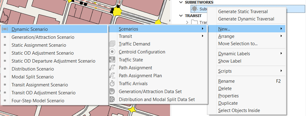
To generate the traffic demand in a Subnetwork, a Static Traversal or a Dynamic Traversal can be used. A Traversal requires input from a previously run static experiment or dynamic simulation replication of the full project network to provide the demand data for the Subnetwork demand.
A Traversal generates a new OD centroid configuration, with a centroid at every entrance and exit as well as the centroids contained in the Subnetwork area. It generates a set of OD matrices corresponding to the centroids with the inner trips which start and finish in the Subnetwork and the gate trips which originate or terminate outside the Subnetwork. These matrices will use the same User Classes and Vehicle Types as the full project network. The corresponding Traffic Demand, containing the traversal matrices, will be generated in the Subnetwork folder.
A Static Traversal will also cordon the transit lines and create new routes and schedules for the Subnetwork estimating the departure times from the first stop within the Subnetwork from the transit times from the route start to the edge of the Subnetwork. These routes will be included in a new Transit Plan for that Subnetwork. This plan, and the transit lines generated by a static traversal, can also be used in subsequent dynamic experiments.
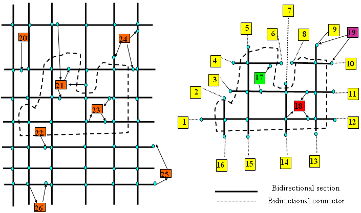
The Traversal will generate centroid configurations as shown below. The new connector centroids are marked in yellow in the Subnetwork and the original centroids retained. Note how:
- Centroid 17: Retains its connections to those sections wholly within the Subnetwork and discards connections to sections wholly outside the Subnetwork.
- Centroid 18: Retains its connections to all its sections.
- Centroid 19: Retains its connections to sections which are linked to a node within the Subnetwork.
The Traversal also generates Transit lines and Transit Plans cordoned from the full project network.
Traversal Options
The options specific to each traversal type are:
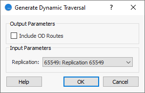
Dynamic Traversal
Include OD Routes: Reuse the OD routes from the full project network. See the OD Routes Section for how OD routes are used.
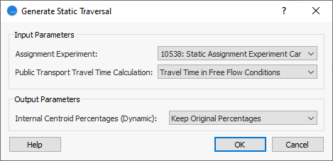
Static Traversal
- Assignment Experiment: Choose the experiment that the traversal matrices will be calculated from. It can be an assignment or an adjustment experiment.
- Transit Travel Time Calculation: select how to calculate the travel time for transit vehicles from the origin of the line to the subnetwork border to update the transit line schedules for the subnetwork:
- Travel Time in Free Flow Conditions
- Total VDF/TPF/JDF Cost
- Function Component
- Internal Centroids Percentages: for the centroids which are not gates to the subnetwork but have been duplicated from those in the global network, there are options for assigning traffic to the connections (see the Centroid Editor for how these percentages are interpreted):
- Keep Original Percentages: keep the Percentage usage as they were set for their corresponding original centroids for dynamic simulations,
- Assignment Percentages: fill in the Percentages automatically with the percentages of usage obtained by the global assignment used to calculate the Traversal matrices,
- Do Not Assign Percentages: Leave the Percentages blank.