Control Plan Editor for Metering
A Metering controls the flow of vehicles past it to regulate the number passing its location. The type of metering is set in the Metering Editorand the data associated with that type of metering is set in one or more control plans for it. A control plan then is included in a Master Control Plan which in turn is selected in the Scenario.
The types of metering available in the metering editor are:
- Green-time metering: The meter works as a traffic light.
- Green-time by lane metering: The meter works as a traffic light but giving green to each lane one after the other from right to left with a delay.
- Flow metering: The meter gives a determined flow rate and lets vehicles go through in platoons of a fixed size.
- Flow-ALINEA metering: The meter implements the ALINEA law ramp metering strategy. In mesoscopic simulation it is treated as a flow metering.
- Delay metering: The meter delays each vehicle by a predetermined time. In meso the delay metering works slightly different compared with micro. The delay metering in meso only ensures that all vehicles will have at least the delay defined in the delay metering. This is different from what is doing the microscopic simulation because in there all vehicles are delayed when they go through the metering.
The control plan policies associated with the metering are set in the Control Plan Editor. The options are:
-
Unspecified: When no control editing has been made.
-
Uncontrolled: When the metering device is assumed to be disconnected.
-
Fixed: When a fixed pattern for control is used. This means that none of the parameters for the metering will vary during the simulation time.
-
External: The parameters initially set can vary and the controller sets limits on the ranges used. The timings or flow rates can then be adjusted by an external algorithm written by the analyst using the Aimsun Next API.
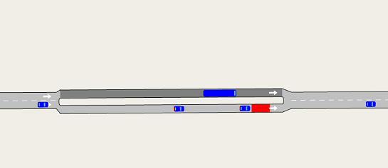
When creating a metering, consider how to model the road network to achieve the desired behavior. In practice, selective metering is often used to control flows i.e. an adjacent lane with no metering where only certain selected classes of vehicles (for example, public service vehicles) are allowed through while others are delayed by the metering. In Aimsun Next, this would be modeled by considering the un-metered lane to be a different road section. For example, the next figure shows a situation where a bus lane is modeled as a separate section to the adjacent lane, also a separate section and a delay metering is applied to the cars, but not to the bus.
Green Time Metering
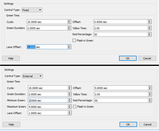
In the metering editor, select either Green Time or Green Time by Lane. The metering will then operate as either a single signal, or as a set of lane signals. In a control plan the green time metering parameters are:
- Cycle: The total time for the cycle, the time of green plus the time of red.
- Offset: The offset of the first green time relative to the initial time of the control plan.
- Green Duration :The time of the green period.
- Yellow Time, Red Percentage and Flash in Green: The yellow time if there is a flashing green light.
If the metering is set to be controlled by lane, an extra parameter is required:
- Lane Offset: The delay before activating the green phase of a lane after the lane on its right has activated its green phase.
If the control type is set to External,two more parameters are required to set the minimum and a maximum green time.
Flow Metering
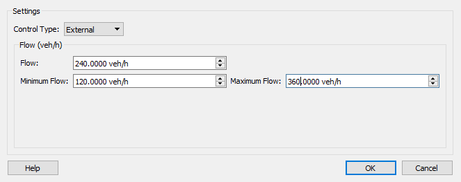
In the metering editor, select Flow and select the platoon size that the metering will permit. The control plan is then edited to set the flow rate in vehicles per hour that is to be achieved with the metering control.
If the control policy is set to External, then two more parameters are required; the maximum and minimum flow rates.
Detailed timing
Note that if flow metering were to require a vehicle to be released at a regular rate, with a release interval measured in seconds, and that this interval was not a multiple of the time step (i.e. a time step of 0.7 seconds and a requested interval of 6 seconds), then the actual release time would be determined to be on the time step closest to the required interval, which might imply the intervals are not always equal and might be N or N+1 time steps long. The flow will however be accurate to within 1 vehicle and within 1 time step.
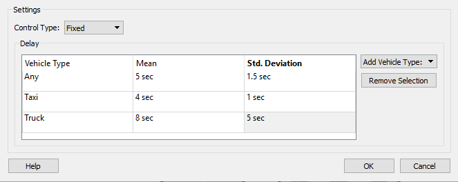
Delay Metering
In the metering editor, select Delay, there are no delay specific parameters for the metering, all the delay timings are set in the control plan. The control plan is then edited to set the delay for each vehicle type with the delay for Any vehicle type being applied to vehicle types not otherwise explicitly specified. The meter then stops each vehicle for a random time, controlled by the mean and standard deviation for the delay for that vehicle type. The delay is not varied externally. A Delay metering is appropriate at a car park entrance or exit or to model a toll booth.
Alinea Law Ramp Metering
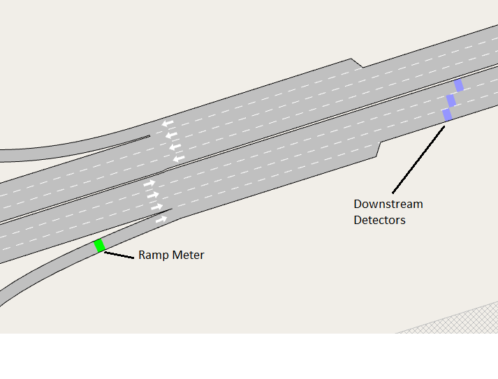
Ramp metering takes place on entrance ramps to a highway to limit the flow of vehicles entering the main road, to maintain non-congested flow on the highway itself by regulating the entrance demand it ensure the capacity of the main road is not exceeded. Ramp meters can be positioned anywhere along the entrance ramp section and can affect any or all of the lanes. Ramp meters are controlled by downstream detectors in the main highway covering one lane each. The Alinea Law is a local traffic-responsive strategy for ramp metering based on a feedback mechanism and was developed by Papageorgiou et al. (1991)
The topology of a ramp meter is shown below. The lane detectors in the main highway are added to a list of detectors in the metering editor. Note that the Alinea Law requires that there is one downstream detector per lane and not a single detector covering all lanes The occupancy measure will be overestimated if a single detector is used as a detector which covers all lanes will record presence every time a vehicle is on any of the lanes, which is higher than the arithmetic average of the occupancy measured by one detector per lane.
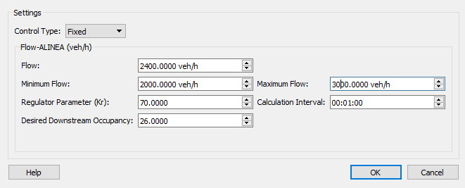
The parameters to be set in the control plan are:
- Flow The initial value of flow to be used before the first calculation,
- Minimum & Maximum Flow The range of flow values.
- Kr A regulator parameter used in the Alinea Law calculations.
- Interval: The interval at which the flow is recalculated.
- Desired Downstream Occupancy The target occupancy for the detectors in the main road.