Aimsun Next: VS-PLUS Interface
Architecture
Communication between Aimsun Next and VS-PLUS uses TCP/IP protocols, where Aimsun Next acts as a server and VS-PLUS as a client. Aimsun Next creates one server for each VS-PLUS controller and each of them connects with a VS-PLUS controller emulator. The connection between each server and its client is identified by a communication port number. The request/response messaging framework uses the SOAP standard.
Relationship between Aimsun objects and VS-PLUS objects
To guarantee a correct connection between Aimsun Next and VS-PLUS, it is necessary to make sure that VS-PLUS objects have a one-to-one correspondence with Aimsun objects. All these correspondences are defined by:
- VS-PLUS Controller: Each VS-PLUS controller must be represented in Aimsun Next as one VS-PLUS-type controller (AVSPLUSCont).
- VS-PLUS Intersections: One VS-PLUS intersection can be represented by one (or more) Aimsun junctions. The AVSPLUSCont must be connected to all Aimsun junctions that form the VS-PLUS intersection.
- VS-PLUS Signal Groups: The Aimsun model must contain the same signal group definition as the VS-PLUS model, with the same turns associated with each signal group.
- VS-PLUS Detector: Each VS-PLUS detector should be modeled with a corresponding Aimsun detector. If the detector corresponds to one physical detector then the Aimsun detector must have, at least, Occupancy as a measuring capability. And if this detector represents a detector for Transit then the Aimsun detector must have, at least, Equipped Vehicle as a measuring capability. All transit lines associated with Transit detectors must be modeled in Aimsun Next as Transit lines with 100% of Equipped vehicles in their Vehicle Types.
- Control Plan: A pre-timed or fixed control plan with the definition of all phases with their durations should be implemented for each intersection controlled by VS-PLUS. It is necessary to set their control type as External. This definition of the control plan will be applied when the VS-PLUS controller is not active.
Aimsun Next – VS-PLUS interchange information
The interchange of information between Aimsun Next and VS-PLUS (synchronization tokens, detector measures, stages, etc.) takes place every second as one of VS-PLUS’s requirements. The detection cycle should therefore be set to 1 second. If the simulation step is not 1 second, the data synchronization rules apply.
Defining VS-PLUS objects in Aimsun Next
The definition of the VS-PLUS objects is done using Aimsun Next and it is based on first defining the VS-PLUS preferences, then defining one VS-PLUS type controller in the Aimsun model corresponding to each real VS-PLUS controller.
The VS-PLUS preferences allow you to specify where the VS-PLUS executable file is located so that when the simulation starts Aimsun Next can also start VS-PLUS automatically.
Note: As with all Aimsun Next objects, their dialogs might or might not include an Attributes tab, depending on whether the object has additional attributes beyond the scope of the standard UI for the dialog.
To set VS-PLUS preferences:
- Select Edit > Preferences > Adaptive Control Interfaces.
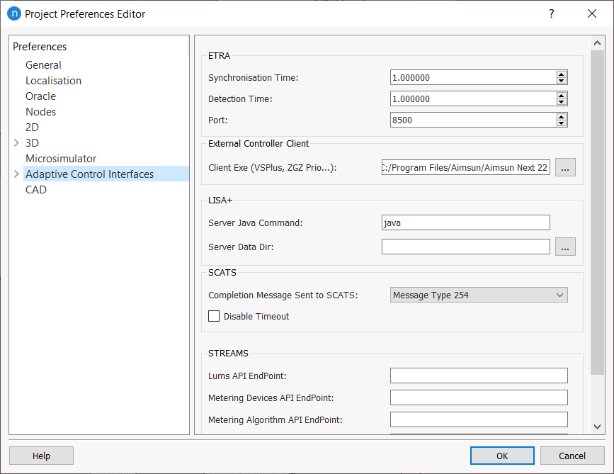
- In the Client Exe (VSPlus...) field, browse to and select the location of the VS-PLUS EXE file.
- Click OK.
To define a controller:
- Double-click a controller in the 2D view to open its dialog.
- In the Type field, select VS-PLUS. This will display the appropriate tabs for the controller.
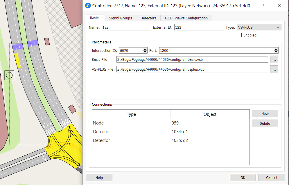
Basics tab
The first step is to set the Basics tab parameters:
- Name: The controller object' name.
- External ID: This ID must match (formerly known as Program ID).
- Intersection ID: VS-PLUS intersection identifier.
- Port: Communication port number for communication between Aimsun Next and VS-PLUS.
- Type: List of different controller types (keep as VS-PLUS).
- Enabled: Tick this option to make sure the controller is active in the simulation.
- Basic File: Path of the file containing the basic VS-PLUS controller information (formerly known as Information File).
- VS-PLUS File: Path of the file containing the VS-PLUS parameters (formerly knows as Parameters File).
- Connections: Defines the connections between the controller and those objects it controls. Click New and then click on an object in the 2D view to add an object. All junctions and detectors controlled by the VS-PLUS controller must be connected and listed here.
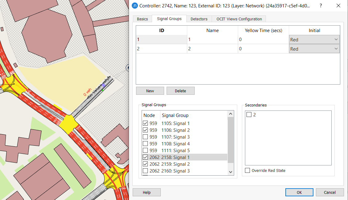
Signal Groups tab
The second step is to establish how the controller ‘sees’ the different signal groups. Each VS-PLUS signal group has the following parameters:
- ID: The VS-PLUS channel or signal group identifier. In one controller these identifiers must be consecutive and defined from 1 to 48. These identifiers determine the order in which Aimsun Next receives the signal state and this order must be the same one that VS-PLUS has in its configuration.
- Name: The VS-PLUS signal group name (optional).
- Yellow Time (secs): This parameter is not used.
- Initial: The initial state of the VS-PLUS signal group at the beginning of the simulation.
Usually, a set of Aimsun signal groups from different junctions is joined into a single VS-PLUS group, which is then managed by the controller. This means that, when a controller activates one of its signal groups, all the signal groups of all the junctions in the controller's signal group are also activated.
This concept is shown below. Here, signal group ID ! is associated with two signal groups in two junctions, so that when the controller receives the order to activate its signal group 1, signals 1 and 2 are activated in both junctions.
Detectors tab
The third step is to establish how the controller ‘sees’ the different detectors in the network.
To add a new VS-PLUS detector:
- Click on the Detectors tab.
- Click New.
- Set the ID for the detector you are adding.
- Select a detector from the drop-down list of available detectors under the column heading Detectors.
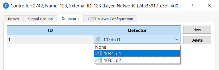
- Repeat steps 2–4 for any additional detectors.
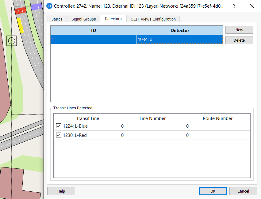
Each VS-PLUS detector has the following parameters:
- ID: Represents the VS-PLUS channel (a number between 1 and 120; not necessarily consecutive). This channel sets the order that Aimsun Next follows to send detector measurements.
- Detector ID and Name: The Aimsun detector associated with this VS-PLUS detector.
- Transit Lines Detected: Defines the Transit Lines associated with one detector. From this type of detector, Aimsun Next sends Transit Vehicle information.
In the figure below, the detector with VS-PLUS channel 1 is assigned to the Aimsun detector with the ID 1034: d1 and two transit lines.
OCIT View Configuration tab
From Aimsun Next 22, the VS-PLUS controller complies with OCIT (Open Communication Interfaces for Road Traffic Control Systems) standards. The OCIT View Configuration enables you to select which graphical elements and which protocols to display in the Controller dialog while running the simulation. When a simulation is running, the controller presents an extra tab, named Simulation Control. This tab displays the elements you specify on the OCIT View Configuration tab.
To set the View OCIT Configuration elements:
- Click on the View OCIT Configuration tab > Graphical View subtab.
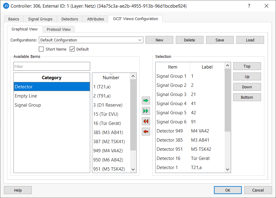
- For Configurations, select Default Configuration (if you want to add a new configuration, click New).
- From the Category list, select Detector, the corresponding Number (use multi-select if required) and click the green arrow to move your selections to the Selection list.
- Repeat step 3 for Signal Group items.
- (Optional) Click Empty Line to insert a space between variables. This can improve the legibility of outputs.
- Use the Top, Up, Down, Bottom buttons to reorganize items in the Selection list.
- Click on the Protocol View subtab.
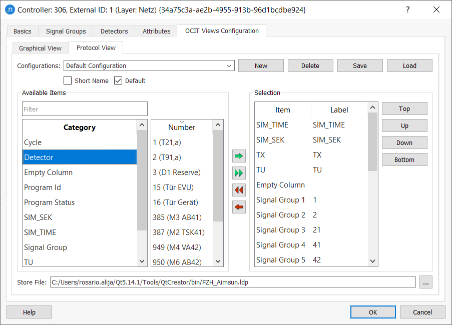
- Repeat steps 3–6 for protocol items on this tab. Note that you can insert Empty Column rather than Empty Line on this subtab.
Running a Simulation with a VS-PLUS Controller
To run the simulation:
- Right-click on the replication and select Run Animated Simulation (Auto). The log window will display any relevant messages, warnings, or errors.
- Open the Controller dialog to view the activated Simulation Control tab.
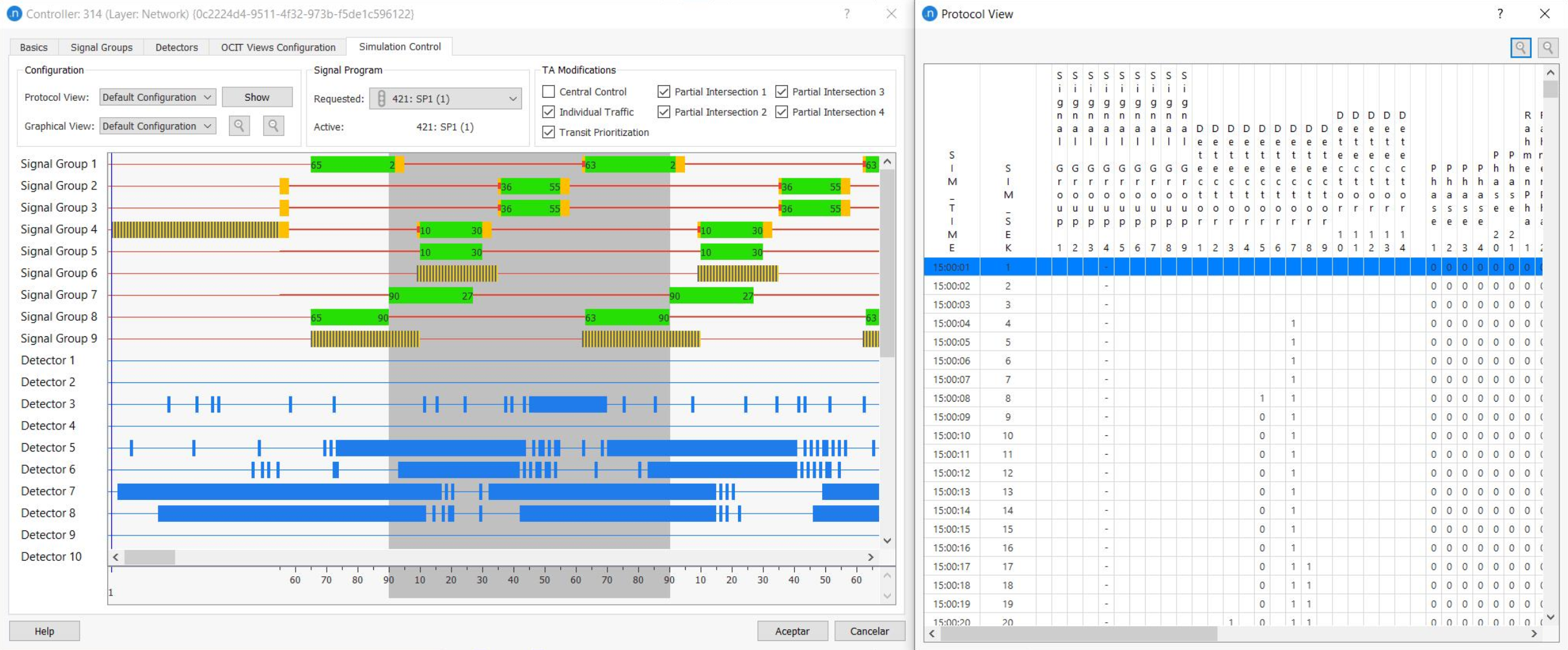
Simulation Control tab
The Simulation Control tab provides provides two views of the control actions: a Graphical View showing the state of phases, stages, and detectors, and a Protocol View which displays details of signal actuations.
The Graphical view is automatically displayed in the tab. Zoom in and out with the magnifying glass icons.
To see the Protocol View in a separate, moveable window, click Show. The screenshot below shows both views during a simulation.