Paramics Importer
The Paramics importer has two main features. The first is the import of geometric data of the network where objects like sections, nodes or centroids are defined. The second is the import of OD matrices and profiles This feature is available when importing geometric data and also afterwards, when geometric data has already been imported. The OD matrix is created using the Centroid external ID’s.
A Paramics network must be imported into a new Aimsun document created with the File : New. menu option. It is not possible to import a Paramics network into a previously existing Aimsun Next network.
Importing from Paramics to Aimsun Next
Importing networks from Paramics consists of reading network files and then creation of all defined elements maintaining a very accurate correspondence between Paramics and Aimsun objects.
Importing a network from Paramics
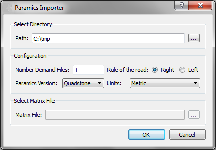
The first step to import a network from Paramics is to set the directory in which the Paramics files are stored. Once the path is selected, the following parameters, are defined as shown in the next figure.
Number Demand Files sets the number of demand files that are defined in the network. Each file contains several OD matrices and is related to a time period.
The Rule of the Road is used to indicate to the simulator which side of the road the traffic drives and is used to set turns in the correct order.
Paramics Version sets the network Paramics Version. It is important to define this parameter because Q-Paramics (Quadstone) and S-Paramics (SIAS)use different formats for some files (i.e. ‘Priorities’ file). Note that only S-Paramics 2000 software models can be imported, Paramics "Discovery" uses a different and closed format.
Finally, Units parameter sets the kind of units that define the coordinates of any point. These are translated to meters in the Aimsun model.
Files are read in the following order: zones, categories, centers, nodes, links, nextlanes, junctions, priorities, matrix, demands, profile, busstops, busroutes, detectors, beacons, and annotation.
The Matrix File field is enabled only when any network has been previously imported (see next Figure). Note that centroid identifiers must correspond with the Aimsun centroid external IDs. If not, there would be incorrectly generated OD matrices. Also, matrices that are imported after the geometrical data will not have all parameters initialized, such as initial time or duration, because those fields are defined in geometrical files. Therefore, we strongly recommend that all files are imported at the same time.
Relation between Paramics and Aimsun objects
Nodes and centroids translation
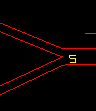
This importer simplifies all kinds of Paramics nodes and classifies them into two categories: junction and ramp. Roundabouts are imported as junction nodes avoiding U-turns and a warning message is printed indicating the node reference, to let the user locate and modify the junction (by clicking on the reference in the warning).
An example of node translation is shown in the next figure. Only nodes with any control plan associated are marked as yellow box.
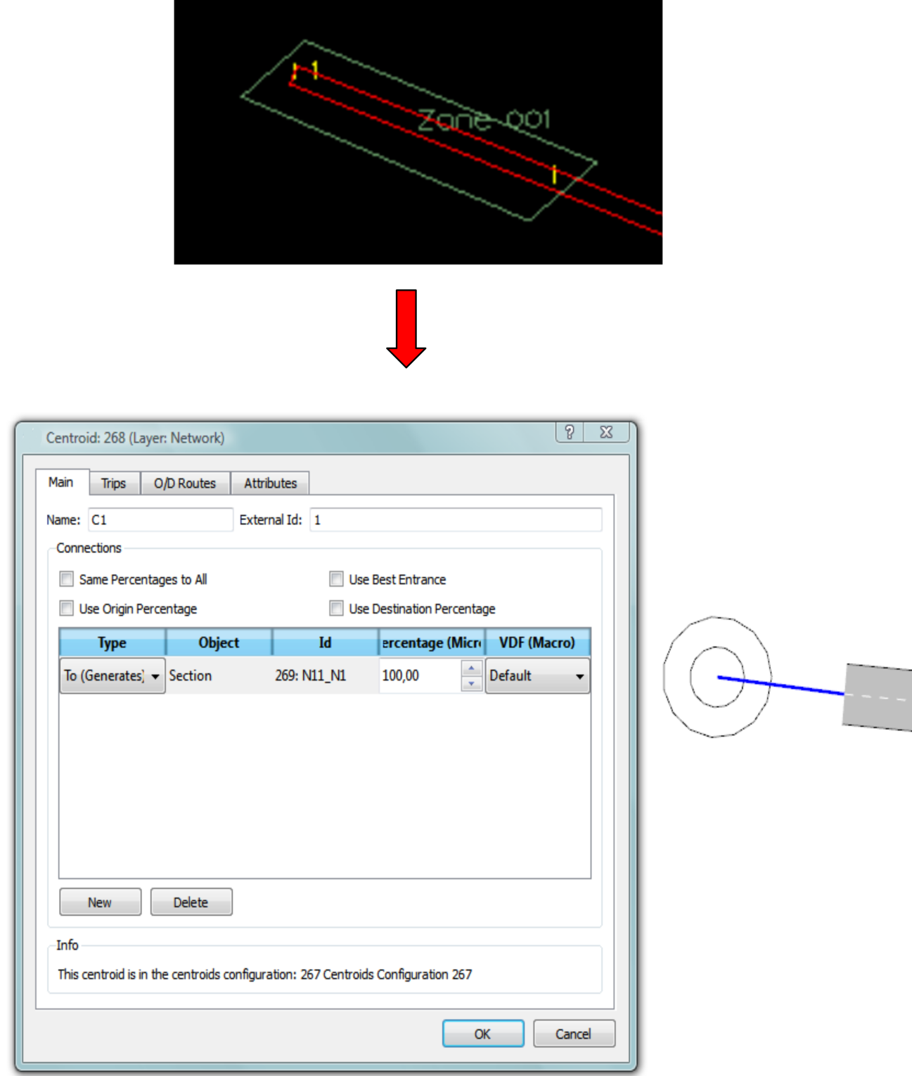
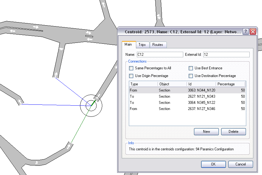
Aimsun centroids and Paramics zones are strongly related. A Paramics zone is defined as an area where vehicles enter or leave the network using the road links contained in that area. In Aimsun Next, links between centroids and section are handled differently, hence centroids are created in the following way:
- The importer locates the node with the least connections that is contained in zone area.
- The position of this node will be the position of the new centroid.
- The Centroid external ID will be set with the zone identifier. - The new centroid will be connected to all sections that end or begin inside the zone area and that are floating sections; this means that one of its extreme points is not connected to any node.
An example of centroid translation is shown in the figures below:
Links - Sections translation
To import sections, this interface obtains all data from Paramics links so generated sections will have the same basic characteristics as their related Paramics links. This includes road type, speed limit, etc.
Link Shape
Each section is limited by two nodes, origin and destination, which give us the position where the section physically begins and ends. To avoid section accumulations on each node, the interface calculates a safety distance that reduces the length of every section. This distance is calculated using the section width and the number of sections that are connected to the node.
Also, sections are moved (depending on Rule of the Road parameter) laterally depending on if they have any parallel section, as next figure shows. It must take into account that only sections that join the same nodes are determined as parallel.
Ramps
Two situations are found in the definition of ramp nodes:
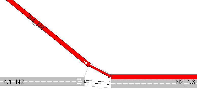
The first is shown in figure below:
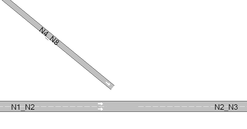
Section N4_N8 has to be connected by a ramp to the section N2_N3. Because section N4_N8 ends near origin node of section N2_N3, the task is to add a new side lane on section N2_N3 and connect section N4_N8 to this new lane. The result of the import is shown in figure below.
The second kind of ramp is showed in figure below.
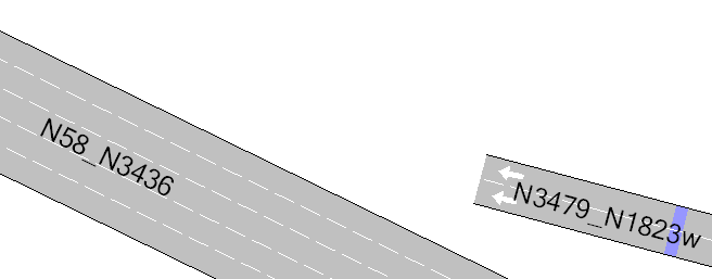
In this kind of ramp, section N3479_N1823w ends in an intermediate point of section N58_N3436. The procedure to import is the following:
- Divide section N58_N3436 in two sections. The point where the section is cut is the projection of the N3479_N1823w end point to section N58_N3436.
- Connect both sections.
- Add a side lane and connect N3479_N1823w to it.
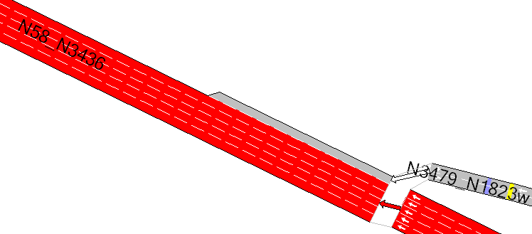
Figure below shows the result of importing a ramp of this type.
If any section has more than one ramp, this procedure is repeated for each one of them.
Turns definition
This interface reads nextlanes and junctions files to import turns from Paramics. Paramics does not explicitly describe junctions where the defaults that it calculates have not been changed therefore, for each node that doesn’t appear in these files, Aimsun Next will create all possible turns, avoiding U-turns.
Nextlanes
Nextlanes file defines specific turns from some lanes from origin section to some lanes of the i-th exit section.
Figure below shows an example of the nextlanes import.
Next Lanes
link 10:445
lane 1 next 1 0
lane 2 next 2 0
lane 3 next 3 0
lane 4 next 4 0
link 437:445
lane 1 next 0 5
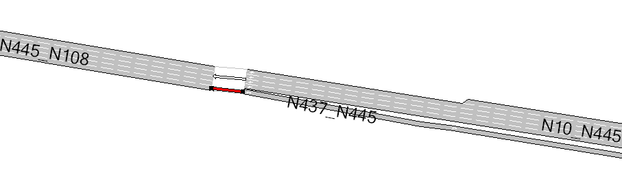
Link 10:445 has 4 lanes at the end of the section. The white turn is the resultant turn of the import, where all origin lanes of section N10_N445 join with the first 4 lanes of destination section (N445_N108).
The second defined turn is the red turn, which joins section N437_N445 with the 5^th^ lane of destination section. Paramics defines two possible exits in node 445, but Aimsun Next only has 1, this is because Paramics also includes barred links (The unused opposite side of link where the opposite direction is explictly modeled, i.e as in a dual carriageway) These links are not imported by Aimsun Next.
Exits are arranged in clockwise or counterclockwise direction, depending on the Rule of the Road. In this example, the vehicles drive on the right.
Junctions
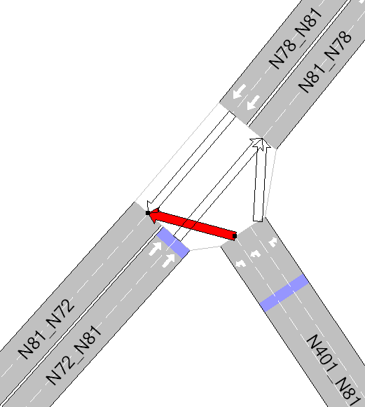
The Junctions file defines, for every available exit, which are the origin lanes to which vehicles can turn (see next figure).
junction 401:81
out 1 lanes 1
out 2 lanes 2 3
Priorities and Control Plans
Paramics priorities are mapped to Aimsun priorities; the next table shows the corresponding relation:
Paramics Priority Aimsun Priority
Minor Stop Medium Yield Major None
Control Plan translation is achieved as follows:
For each possible turn, this interface assigns to it a signal group, so when a phase contains a turn, automatically it adds the related signal group, avoiding barred turns.
The Paramics importer only imports fixed control plans, so the Paramics max parameter, which initializes the Minimum Green and Max-Out parameters of an actuated control plan in Aimsun Next, is not taken into account in fixed control plans but, in actuated ones, it is used to draw the control plan in its editor.
Vehicles
The Paramics importer creates Paramics vehicles setting the Aimsun vehicle ‘car’ default values to all attributes but Length, Width, Maximum Speed, Maximum Acceleration and Maximum Deceleration, which values are adopted from Paramics Vehicles.
OD matrices
OD Matrices are created from data obtained by processing the profiles, matrix, vehicles, and demand files.
Paramics profiles control how the demand varies over a modeled period. The Paramics "matrix" file selects which profile is applied to a trip, the Paramics demand.X file gives the OD total for the period X and the vehicles.X file determines how that demand is split between vehicle types. The algorithm to create the is
Determine which time duration is  modeled from the Paramics "configuration" file
for each 5 min time interval in that duration
    for each cell in the OD matrix
        Find the profile ID from the "matrix" for this cell
        Find the profile multiplier for the interval from the "profiles" file
        Get the vehicle proportions from the vehicles file or the vehicles.X file (It might vary by period)
        Multiply and allocate to an Aimsun OD matrix for this vehicle type and interval
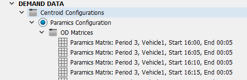
This will generate a set of OD matrices, one for each combination of vehicle type, time interval as shown below with matrices imported for Paramics period 3 ( from 16:00) for vehicle type 1.
Demand Weight
Paramics has the capability to apply a global weight to the demand. This feature is found in Aimsun Next in the Traffic Demand Object and if a demand weight is used in the Paramics model, it should be reproduced here in the Traffic Demand. The Paramics importer will import the matrices as they exist in the model files before applying any global demand weighting.
Transit Lines
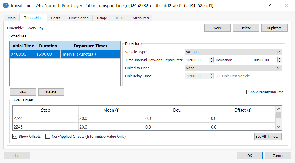
The first step to import transit lines is to create all bus stops in the network. Then this interface creates all defined Paramics public lines and sets the time schedules for each one.
The route of each public line is built taking the sections between nodes.
Note that Aimsun Next only allows one bus stop to be added in a section. If there is more than one bus stop on a section that is related with the same public line, it won’t be added to the public line.
The figure below shows an example of transit line translation.
Detectors, Beacons (VMS) and Annotations
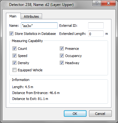
Detectors are placed at the distance from the beginning of the section specified in Paramics Detectors file.
Next figure shows an import of a Paramics detector. Default parameters are checked on each new detector.
Paramics beacons, as with detectors, are placed at the distance from the beginning of the related section. The user can add any text to every VMS.
In order to import annotations without any problems, be sure that the text coordinates format is the following:
(xcoord_[m,ft],ycoord_[m,ft],zcoord_[m,ft])
where [m,ft] means that it is read m (meters) or ft (feet) and blank spaces are marked as ‘_’