Saturn Importer/Exporter
Saturn is a highway assignment software suite developed by University of Leeds. It is used to model strategic road networks using static assignment methods. Aimsun Next can exchange data with Saturn by reading its input DAT files (and the included files that file specifies) to build an Aimsun traffic network and demand matrices, and by exporting an Aimsun traffic network and demand matrices to write new Saturn format files.
This interface, requires a license for both Aimsun Next and for the Planning Software Interface extension.
Import from SATURN to Aimsun Next
The options for importing a Saturn model into an Aimsun traffic network are:
- Import a Base Network: A Saturn model is imported and a new network is created from the Saturn files.
- Update a base Network: A Saturn model is imported into an existing network which is updated e.g. by creating new matrices for different time periods or by creating Attribute Overrides or Geometry Configurations to hold the differences between the existing network and the imported Saturn model.
- Update the demand: Import the demand from a Saturn model and update the demand in the Aimsun project.
Import from Saturn is started from the menu File : Import : Saturn Network.
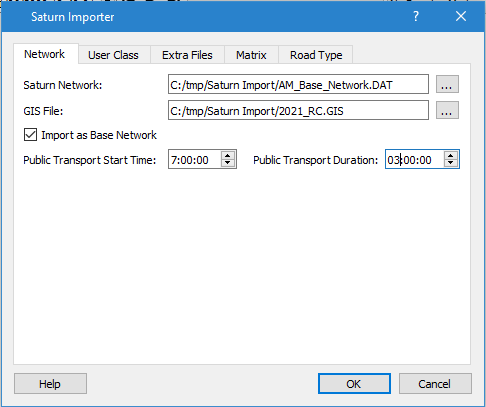
The Saturn network and an associated GIS file are specified here and the option to Import as a Base Network If this option is selected, the whole network is imported and must be imported into an Aimsun document which contains just the template for the model, i.e. the user classes, trip purposes, road types, and lane types, etc. If the Saturn model is imported as a base network twice, it will be duplicated in the Aimsun document. If this option is not selected, then, as a network is imported, differences between the road network will be detected and stored as an Attribute Override or as a Geometry Configuration which will hold just the differences between the two networks.
The network data imported from Saturn includes the road network data of links and nodes with the signal control plans. The matrices can be imported separately or can be imported with the network. The latter option, simultaneous import, is advised as the network file contains parameters that modify matrix values (i.e. the GONZO parameter) which will be used if the imports are done simultaneously but will be lost if they are done separately. The Saturn importer will also create the Volume Delay Functions from data stored in the Saturn network and import Saturn Route files.
When the Saturn DAT file is specified, and before the network is imported, the file is scanned to set up the user classes and vehicle types.
Network Import
The geometric data (including control plans and routes), is imported from the Saturn network file. Link shapes are imported by adding a Saturn GIS file. In area 77777 of the Saturn GIS file, some link intermediate points are defined, Therefore adding a GIS file in the dialog implies that links will be imported as polylines and will have shape rather than be point to point links.
Initially the model should be imported as a "base network" into an empty Aimsun document. The transport network will be created according to the nodes and links in the Saturn Model. Subsequently, if a Saturn model is imported and the option Import as a Base Network is not selected, then the import process finds the differences between the imported network and the current network and creates an Attribute Override or a Geometry Configuration to hold the differences. If the topology of the network remains the same, i.e. the same road sections are present but for example, speed limits have changed, then the differences are stored as an Attribute Override. If the road network has changed, for example a junction has been re-engineered or a new road layout introduced, then the differences are stored as a Geometry Configuration. If the signal control plan has different timings in the second imported network it will be imported as a new control plan and given the name of the file from which it was imported to differentiate it from the base model control plan.
The Saturn import process distinguishes between three groups of Saturn nodes: the first group contains centroids; the second group contains priority junctions, traffic signals, dummy nodes, roundabouts, and roundabouts with U-turns, while the third group contains external nodes.
There are two kinds of centroids, external centroids, and inner centroids. The external centroids are used to provide vehicle entry points into the network. They are connected to the sections ending or beginning at external nodes. These nodes are not transferred into the Aimsun network.
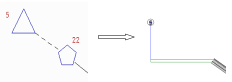
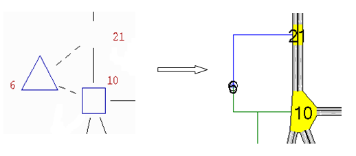
Inner centroids are used to simulate network parking areas located between two inner nodes.
Roundabouts
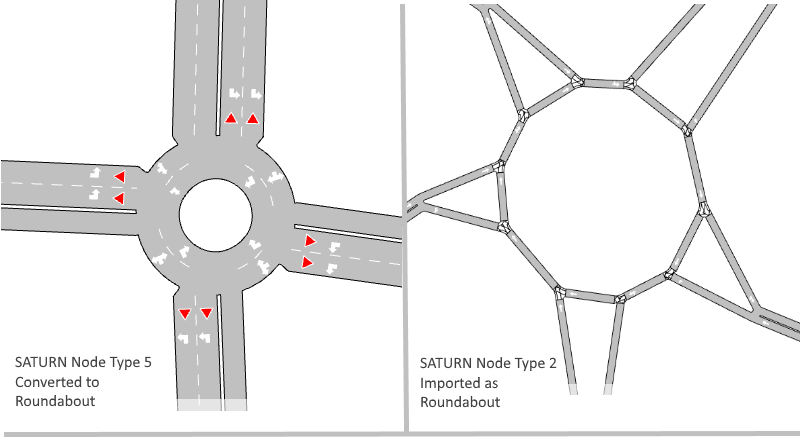
Nodes that are classified as SATURN Node Type 2 (Roundabout) or 5(Roundabout with U turn) are imported as roundabouts. Nodes of type 2 are assumed to be the constituent nodes of a roundabout and are imported as individual nodes into the Aimsun network. Nodes of type 5 are assumed to be a single SATURN node representation of a roundabout and are expanded to a circular diameter roundabout with a default diameter of 5m which can subsequently be edited manually to match the actual road topology. Note that SATURN does not supply information for roundabout diameter or any more detailed layout for type 5 nodes.
Road Sections
Road sections are imported with the parameters specified in the Saturn file and link the appropriate end nodes. Note that Saturn has no need for road sections to reflect the physical geometry of the road network and therefore the network will be stylized and the layout of junctions might look substandard. This only requires editing if the network, or a subnetwork is to be subsequently be used in a dynamic simulation.
Because a road section length includes bends and turns, it can not be equal to the geometrical distance between nodes. Therefore, every road section has an extra Saturn attribute that defines the real length of the section.
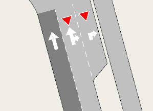
Road section lanes are set depending on the number of lanes specified and the flags B and F, which are found in the link description of the .DAT file. Flag B sets an additional bus-only lane and Flag F sets an additional flared lane.
Road Types
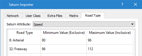
The Road Type tab is used to infer the road type from the SATURN parameters for each link using either the speed or capacity values for the imported section to infer its type in the Aimsun model.
Turns and Control Plans
Within Saturn, specific origin lanes are assigned to turns, but not specific destination lanes, therefore, in the imported model, turns originate from a set of lanes but terminate in all entry lanes in the destination section. Turn priorities in the imported model are assigned as they are defined in the Saturn network. The Saturn saturation flow value is also imported as a "Saturn Saturation Flow" attribute for each turn.

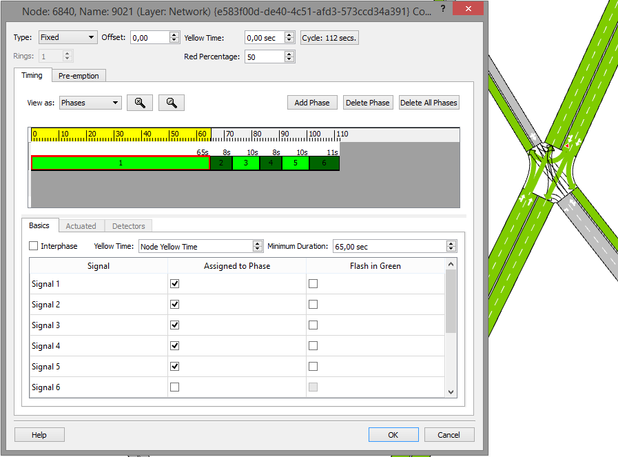
After every stage, but only if intergreen time is greater than 0, an interphase period is created. The control plan type is always Fixed and the Offset value is defined by the Saturn network file. The cycle time is the result of adding all time phase and interphase periods.
User Classes
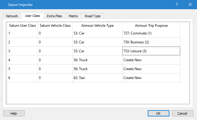
When a SATURN Network file has been specified, it is opened and the user classes and vehicle classes are read from it. These are used to populate the user class list in the "User Class" tab of the import dialog so these classes can be mapped to the classes in the Aimsun template.
Demand Import
First, to ensure the matrices are imported correctly, the Aimsun centroid external identifiers must be edited to match the Saturn centroid identifiers if this was not automatically done on import. By default, when a Saturn network is imported, centroids from the Saturn model are created in Aimsun Next with an internal name "Cxxxxx" and an external ID "xxxxx" where "xxxxx" is the centroid ID in the Saturn DAT file.
The matrix files are specified individually and imported as text files. As many matrix files as required for the different user classes can be specified. The matrices must be dumped from .ums file using Saturn dump options. The Saturn importer only loads matrices in standard real format or standard integer format options. While it is advised to import the matrices and network simultaneously, as some network parameters also affect the matrices, it is possible to update matrices in an existing Aimsun document at a later time.
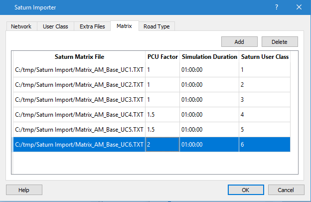
The parameters PCU’s factor and Total Simulation Time are used to calculate the multiplication factor for the matrix. The first defines the equivalence factor between PCUs and VPH (Vehicles per Hour), the second is used to obtain matrix values (trips) for total simulation time.
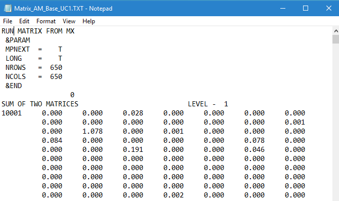
The matrix file must be a trip matrix created in SATURN and containing the following header records:
- RUN runname
- &PARAMS NROWS=nc,NCOLS=nc,MPNEXT=T, &END
- TRIPS PCUH
- matrixname
This header is followed by the zone trips. in the format "origin zone, list of trip rates" See the SATURN v11.3.10 Manual, section 4.1 for more details.
Traffic State Import
The Aimsun model might use a Traffic State to provide the flows in a simulation. This requires data from the SATURN model is provided in a TXT file in the following format:

- Cols 1-5 origin node (A)
- Cols 6-10 center node (B)
- Cols 11-15 destination node (C or D)
- Cols 16-29 flow
If any of those nodes is a centroid, a ‘C’ tag must be added at the first column of the node (column 1 in origin node and column 11 in destination node).
This data is then imported with the SATURN Model.

Cost Functions Import
The SATURN importer will create a default SATURN VDF Function which reads parameters from road sections and returns a volume related delay for that road section. The parameters read from the SATURN file are:
- Is Buffer Zone Link
- Flow Delay Power
- Time Speed Free Flow Condition
- Time Speed Capacity
- Stacking Capacity
- User Class Costs ( PPM PPK)
- Link Length
These values are held as road section attributes:
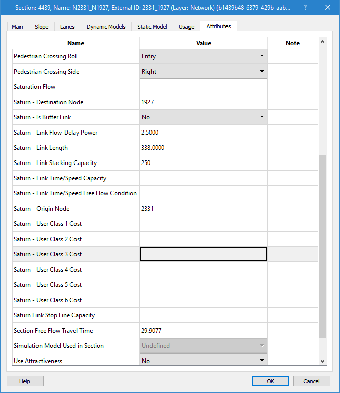
The stacking capacity parameter for a link indicates the space available for queues in the section, a simplification of geometry editing to estimate road space. These values might be negative to indicate that a “link chain” can not extend through this link which affects blocking back behavior. The absolute value of the stacking capacity is used to estimate the volume delay.
The 88888 record at end of a SATURN data file specifies the PPM and PPK values used in the generalized cost for each vehicle type referring to the "Pence Per Minute" and "Pence Per Kilometer".
The SATURN Link Length is used as a correction to the computed length of the road section. If no geometry is imported, the straight line distance between nodes can be shorter than the actual distance on a winding road. This attribute corrects that value.
Routes Import
Two different route types can be imported from a SATURN network file. The first defines Transit Lines, the second defines paths between two centroids.
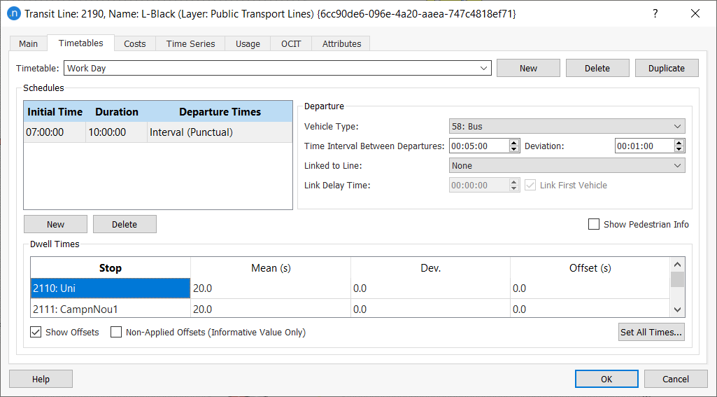
Transit Routes
When importing Transit Lines, bus vehicles are assigned to the routes as the default option. Reserved transit lanes on the rightmost or leftmost side are usually defined, depending on LEFTDR parameter.
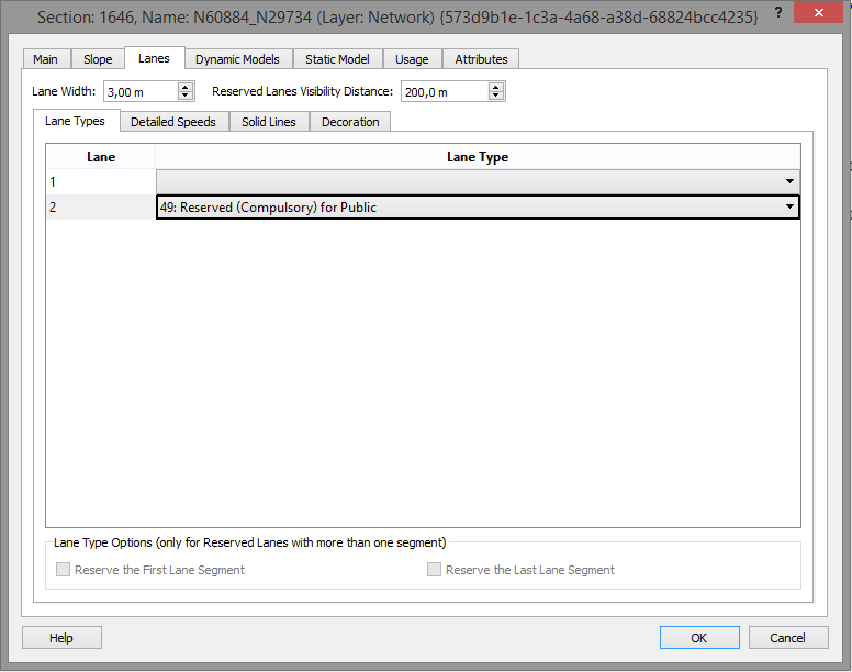
The Mean value is calculated from the bus frequency value, which is specified in the network file. In SATURN, the frequency is specified in vehicles/hour, In Aimsun Next, the inverse of the frequency is required in minutes between buses.
OD Routes
OD routes are used to provide static paths for vehicles to follow. They are imported from a .TRP file specified in the "Extra Files" tab of the import dialog and form an Aimsun paths object.

KNOBS file
A SATURN KNOBS file is a source of additional data for the sections, turns, and centroids in the model. The KNOBS file is a text file with a defined separator between fields ( , ; :) and a choice of formats specified by the *DUTCH" Parameter. Refer to chapters 6 and 15 of the Saturn manual for the two format options.
When a KNOBS file is added to the list, mappings between the fields in the file and the attributes of the section, turn or centroid must be supplied, the KNOBS mapping dialog is shown automatically when a file is selected.
The columns in the KNOBS file are listed and attributes from a section, turn or centroid selected to receive the imported values. To add a new attribute to hold the KNOBS data from a column, select New and label the new Aimsun attribute.
Data can be imported directly with no translation using the "Direct Column option, it can also be translated on import, for example, translating travel time to speed for a section. The target attribute can also be refined by lane, or vehicle class.

Exporting from Aimsun Next to SATURN
Exporting to SATURN from Aimsun Next can be used to provide a skeletal network file and a set of matrix files suitable for input to SATURN. The selection of the control plan, transit, geometry configurations and the demand for the network and matrices export is controlled by selecting a scenario which has the appropriate objects specified.
The export dialog is used to select the scenario, the destination folder for the exported files and the filenames to be used.
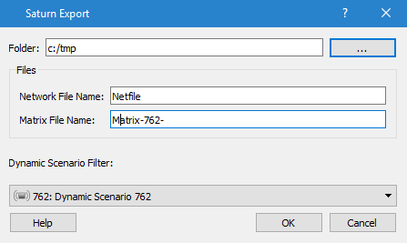
Exporting a Network to SATURN
The network file containing geometric data with the control plans for each signalized node is exported. It is not necessary to specify the extension of the file, this interface always generates 'DAT' files. Only fixed control plans are exported from Aimsun Next to SATURN.
Exporting OD Matrices to SATURN
Matrix Export from Aimsun Next generates as many files as there are OD Matrices are defined in the traffic demand object specified in the chosen scenario. These are named “Matrix File Name value”+X, where X is the number of the matrix that has been exported. All generated files will contain one single OD Matrix with the LONG parameter initialized to TRUE (see SATURN User Manual, chapter 4).
Params Area Export
The following parameters are initialized with their default values:
- DUTCH = F
- KNOBS = 0
- KONAL = 0
- IFCC = T
- IFRL = F
- NO333C = F
- MAXZN = 500
- LEFTDR = T
- XYUNIT = 1.00
- EZBUS = F
- NOMADS = 1
- GONZO = 1.0
- SPEEDS = T
- XYFORM = 5
Node, Turn and Link Area Export
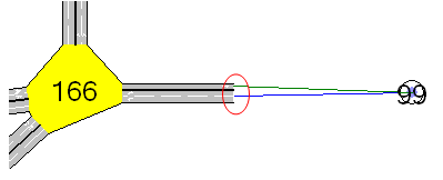
All nodes (including centroids) have their own id linked to an Aimsun external id, so the user can check the export process is correct. The only exception is the external nodes. The figure below shows two sections connected to a centroid, Aimsun Next does not need to create any node, so an additional id is generated for each section.
The saturation flows of every turn are calculated using the TRL RR67 formula:
SatFlow (pcu/h) = ((1940 + 100\*( linkWidth(m)-3.25 ) + IF( Nearside? = ’N’; 140 ) –
42\*gradient(%) – IF( Opposed?=’Y’;230 )) / (1 + ( 1.5\*ProportionTurn / IF(RadiusForTurn=0;1;RadiusForTurn) )) \* nbLanes
Where:
- Nearside? – True if the link has the section slowest lane of the section as one of its lanes.
- Opposed? – True if the link has a link that intersects with it and has its green time in the same stage.
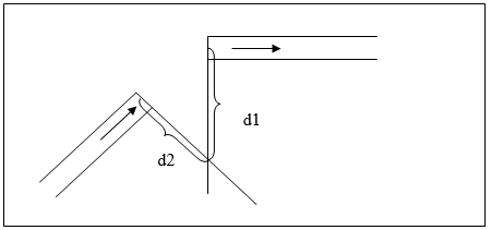
- RadiusForTurn in a turn – max(d1, d2).
- RadiusForTurn in a link – min (Radius of turn of each turn in the link).
Centroid Connector Export
This area contains the centroids connections.
Node Position Area Export
This area contains the node positions. All SATURN nodes have their coordinates in the interval from 0 to 99999, so networks that exceed this bounding box will not be loaded correctly in SATURN.
The procedure to calculate the coordinates for SATURN points is the following:
- Calculate the minimum X coordinate and minimum Y coordinate.
- Subtract those values from all point coordinates (x and y coordinates respectively).
As a result of this procedure, all points in the Aimsun Next model are moved to the minimum bounding box defined by (0,0) and (X max, Y max) points. If Xmax, an Ymax, are less than or equal to 99999 then all points will be exported correctly to SATURN, otherwise, there will be some points out of bounds.
Transit Area Export
This area is filled using the following format:
- Cols. 2 - 5 The “name” of the route (which may, for SATURN 9.1, be alpha-numeric when previously it was solely numeric).
- Col. 6 This field is not initialized.
- Cols. 7 - 10 The route frequency in buses per hour (which could be zero for vehicle routes).
- Cols. 11 - 15 The number of nodes through which the route passes which specifies the number of node entries following.
- Cols. 16 - 20 The first node on the route.
- Cols. 21 - 25 The second node on the route etc. up to column 80.