Aimsun Next: SCATS RMS Interface
Architecture
The communication is between Aimsun Next and the SCATS RMS, software that emulates the operation of up to 300 SCATS compatible Ramp metering controllers, developed by the Road and Maritime Services organization in NSW Australia. The interprocess communication uses a client server model where the communication channel is made using sockets (TCP/IP) with Aimsun Next acting as a server and the WinTraff process acting as a client.
The SCATS RMS interface can be configured to produce debugging information. This option is selected in the Scenario Editor. When this option is active, Aimsun Next will generate log files stored in the same folder as the Aimsun Next document. The file names are (where X represents the communication port of the controllers):
- SCATSDetectorMetX.log: Log of detector state
- SCATSmessagesX.log: Log of messages sent/received
- AimsunNextRampMeteringStateX.log: Log of ramp metering controller changes
Relationship between Aimsun objects and SCATS RMS objects
To guarantee a correct connection between Aimsun Next and RMS, it is essential that the RMS objects correspond with the Aimsun objects. Therefore the following rules must be adhered to:
- SCATS Ramp Controller : Each SCATS Ramp Controller has to be represented in the Aimsun model as one SCATS-RMS type controller, setting the SCATS Ramp Controller name in “Name” field.
- SCATS Intersections: One SCATS intersection can be represented by one (or more than one) modeled junctions. The SCATS-RMS controller must be connected to all Aimsun junctions that form the SCATS intersection.
- SCATS Detector: Each physical detector in SCATS Ramp Controller has to be modeled as one modeled detector. The modeled detector must have, at least, Count and Occupancy as measuring capabilities.
- Ramp Metering: Each Ramp Metering controlled by SCATS-RMS, must be defined as a Flow metering.
- Control Plan: For each Ramp Metering controlled by SCATS-RMS, its initial flow must be defined and the control type must be set to “External”](ControlPlanEditing.html#control_plan_editor_metering).
Aimsun Next - SCATS RMS interchange information
Aimsun Next provides SCATS with the detector actuation data at each simulation step and SCATS responds with the changes of ramp metering parameters (platoon, green time, and red time). SCATS RMS assumes a data transfer is made every second and 1 second of data is available from the detector. The detection cycle should therefore be set to 1 second. If the simulation step is not 1 second, the data synchronization rules apply.
SCATS RMS objects definition in Aimsun Next
The definition of the SCATS objects specifies one SCATS-RMS controller in the Aimsun model for each SCATS Ramp metering controller. The Adaptive Controller editor for a SCATS controller is shown below.
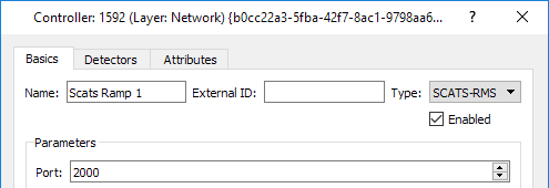
In the Basics tab the options are:
-
Name: Ramp Metering Controller name in SCATS RMS.
-
Port: This communication port number defines the communication between Aimsun Next and the SCATS RMS (this is common to all SCATS controllers).
-
Connections: Defines the connections between the controller and those devices under its control. Links are made using the New button or the Connection tool. All nodes and detectors controlled by SCATS RMS must be connected.
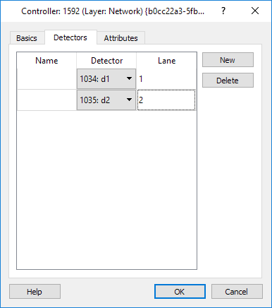
Detectors Tab
The third step is to establish the controller's links to the associated detectors. To add a new SCATS RMS detector:
- Click on the New button,
- set the ID and
- select a detector from the list of detectors connected to the controller.
The attributes for each SCATS RMS detector are:
- Name: represents the SCATS RMS Identifier.
- Detector ID and Name: is the modeled detector associated with this SCATS RMS detector.
- Lane: represents the SCATS RMS lane.