SYNCHRO Importer and Exporter
Synchro is software from Trafficware for optimizing traffic signal timing and performing capacity analysis. The software optimizes splits, offsets, and cycle lengths for individual intersections, an arterial road, or a complete network
Aimsun Next contains both an importer for Synchro to import Synchro networks and Synchro signal timings and an exporter to create a Synchro network from an Aimsun traffic network, or from part of an Aimsun traffic network. The interface reads and writes CSV files compliant with the UTDF (Universal Traffic Data Format) Combined format defined by Trafficware
The Synchro Importer and Exporter is aimed at using Synchro in combination with Aimsun Next to perform the following tasks:
- Use Synchro to optimize the signal timings of a network modelled in Aimsun Next and then quantify the network performance with a micro or meso simulation.
- Undertake a Level of Service analysis in Synchro of a network modelled in Aimsun Next.
- Create a draft Aimsun model from a Synchro network.
Synchro Optimization and Analysis
Starting from a calibrated Aimsun model, the workflow for the first two tasks is to export the network from Aimsun Next to create a network in Synchro, use Synchro to optimize the signal timings, then re-import the times to Aimsun Next.
In detail the tasks are:
- If only a portion of the whole network needs to be exported, define a SubNetwork.
- If the turn volumes have to be read from Traffic States, create the Traffic States (either manually or with the results of a static assignment) and group them in a Traffic Demand.
- If the model contains several Control Plans, create a Master Control Plan containing the Control Plan to be exported.
- Launch the Synchro Exporter and select the output UTDF file to create either the whole network or a Subnetwork, a Master Control Plan, and either a Traffic Demand based on Traffic States or a Replication (meso or micro) to provide the turn volumes.
- Perform the signal optimization and/or the Level of Service analysis in Synchro.
- Launch the Synchro Importer to import the optimized signal timings in Aimsun Next.
Synchro Import
For the third task, to create a draft Aimsun traffic network, the workflow is to create a new Aimsun document and import the draft geometry, a Control Plan and a Traffic Demand composed of Traffic States from an existing UTDF file.
The information that is imported includes:
- geometry of the network
- signal phasing and timings
- turn volumes
Synchro Importer
The Synchro Importer reads a CSV file in UTDF Combined format and imports the signal phasing and timings into an existing Aimsun model, or it creates a new draft network using the geometry contained in the file, a Control Plan using signal phasing and timings and a Traffic State using the turn volumes.
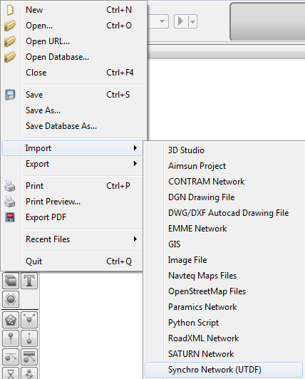
The Synchro Importer is launched from the File menu, Import, Synchro Network (UTDF) option as shown in the figure below.
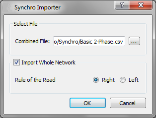
The import dialog selects the Synchrofile to import and whether to import the whole network, or just the signal information.To import the signal information only, the Import Whole Network option is left unchecked.
Importing the signal information
The Importer will map Aimsun Nodes to Synchro Nodes using the Synchro Node ID attribute and Aimsun Next Turns to Synchro Lane Groups using the cardinal directions as defined in Table 1 below.
A new control plan containing the phasing and timings defined in the UTDF file will be created. Note that the signal groups are not modified,therefore the assignment of the phases to the lane groups must be feasible with the signal groups as defined in the Aimsun model
Importing the whole model
Create a new Aimsun project from a template and launch the Synchro Importer. To create a model from an UTDF file, the Import Whole Network option must be checked and the rule of the road (driving side) must be provided.
The Synchro Importer builds the geometry creating a Section for each Link and a Turn and a Signal Group for each Lane Group. It creates a Control Plan with the Timing Plan and Phasing information, and creates Traffic States: one for light and one for heavy vehicles with the Turn Volumes. A Master Control Plan containing the Control Plan, a Traffic Demand containing the Traffic States, a Scenario, a Microsimulation Experiment, and a Replication are automatically configured.
Synchro Exporter
The Synchro Exporter creates a UTDF file, containing the geometry of the network, the turn volumes and the signal timings.
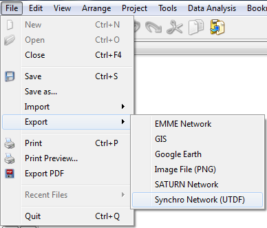
The Synchro Exporter is launched from the File menu, Export, Synchro Network (UTDF) option
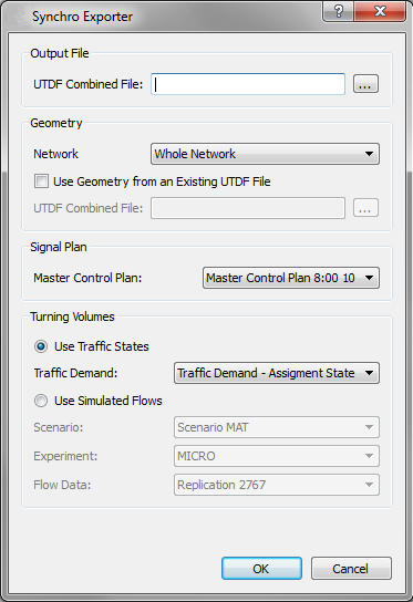
The dialog that appears allows the user to select the file to be created and the source of information about the geometry, the signal plans and the turn volumes.
The path and filename of the output file is set in UTDF Combined File, under Output File.
The geometry can be either taken from the whole network or from any existing subnetwork that is listed in the drop-down list under Network. Aimsun Next models different types of road infrastructures (freeways, signalized roads, etc.) in the same model and different sizes of networks (from an isolated intersection to a whole city), while Synchro is mainly intended for isolated signalized intersections or corridors of signalized intersections. Exporting just a Subnetwork allows an existing, larger model to be used in a Synchro study and also allows the effect of optimizing a corridor to be studied in a wider context, i.e. the effect on route choice.
If the Use Geometry from an Existing UTDF File option is checked a previously exported UTDF file can be used to provide the traffic network rather than to generate it from Aimsun Next. This option conserves any subsequent editing done in Synchro, when repeating the export in order to test a different signal plan. In this case, the geometry will be taken from that file, while the signals and the turn volumes are taken from the Aimsun document. For this option to work, the UTDF file needs to have the same node identifiers as the modelled network, for example, from a previously exported file and the network topology must be the same.
The signal phasing and timings are taken from the Control Plan contained in the Master Control Plan chosen from those listed under Signal Plan. Note that only Master Control Plans containing a single Control Plan are listed because Synchro can only handle one set of phasing and timings for each intersection. Therefore, it is only possible to export a single control plan at a time.
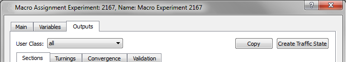
The turn volumes can be either taken from a set of Traffic States, or from the outputs of a dynamic simulation. To use the turn volumes of a static assignment, create the Traffic States from its results using the *Create Traffic States" option in the Experiment Outputs Tab
If Use Traffic States is selected, a Traffic Demand containing the Traffic States to use must be chosen from those listed. To be listed, a Traffic Demand must be based on Traffic States and have one or two Vehicle Types: the Traffic State of the Vehicle Type having a PCU of 1 defines light traffic, while that of the Vehicle Type having a PCU greater than 1 defines heavy traffic. Light and heavy flows are added to calculate the total volume and then the percentage of heavy vehicles is calculated.
If Use Simulated Flows is selected, a Dynamic Scenario, a meso or micro Experiment and a Replication must be chosen from the drop-down lists. The selected replication has to be simulated with the calculation of outputs for Turns and Nodes active or the data has to be retrieved from the database. The turn flow for any Vehicle Type having a PCU of 1 defines light traffic, while that for any Vehicle Type having a PCU greater than 1 defines heavy traffic. Light and heavy flows are added to calculate the total volume and then the percentage of heavy vehicles is calculated. Note that the start time and duration of the Master Control Plan selected under Signal Plan determines the interval of the outputs that will be exported.
The turn volumes produced by a static assignment represent the total demand, while those produced by a meso or micro simulation represent the demand served by the actual signal timings.
The Exporter assigns a new unique ID to all the nodes exported to Synchro (intersection, bend, and external nodes). It adds a column to the modelled nodes, called Synchro Node ID, where the automatically generated Synchro ID for the exported nodes is stored, and it adds two columns to the modelled sections, called Synchro Node Origin and Synchro Node Destination where the Synchro IDs of the extremities are stored.
These attributes are used by the Exporter, in the case where Use Geometry from an Existing UTDF File is checked, and by the Importer, in the case where Import Whole Network is not checked, to establish a correspondence between nodes and sections in the Aimsun model and the nodes and links in a UTDF file.
The Exporter assigns the cardinal directions to approaches and lane groups according to the actual angle in the model, It does not apply any automatic rotation to simplify diagonal intersections with four or less legs.
Approach and lane group designations table:
Angle Direction
-π/8 < α ≤ π/8 EB π/8 < α ≤ 3π/8 NEB 3π/8 < α ≤ 5π/8 NB 5π/8 < α ≤ 7π/8 NWB 7π/8 < α ≤ -7π/8 WB -7π/8 < α ≤ -5π/8 SWB -5π/8 < α ≤ -3π/8 SB -7π/8 < α ≤ -π/8 SEB
Ideally, it is possible to change the values stored to match those of an existing Synchro network even if not exported from Aimsun Next, but the user must ensure that the orientation of the network and the topology are the same.
Naming conventions for signal control parameters
The following table shows the relation between the names used in Aimsun Next and those used in the UTDF file for signal control parameters.
Naming conventions for NEMA parameters:
Aimsun Next UTDF -------------------------------------------- ----------------- Barrier, Ring, Position BRP Minimum Green, Maximum Initial Green MinGreen Max-Out MaxGreen Passage Time VehExt Time Before Reduce TimeBeforeReduce Time To Reduce TimeToReduce Passage Time MinGap Yellow Time Yellow Interphase Time AllRed Recall Recall
Permissive Period From, Permissive Period To and Force Off are initialized automatically.